Introduction: What "High Bay Replacement" Actually Requires
The Definitional Problem
The high bay lighting market is in a period of accelerated transition. The industrial and commercial LED lighting market grew from $77.39 billion in 2025 to $93.19 billion in 2026, driven in part by "growth in retrofit installation projects" and "rising demand for high bay and panel fixtures." The LED high bay fixtures market alone was estimated at $3.2 billion in 2025, with a projected compound annual growth rate of 6.5% through the forecast period.Retrofit activity is not a niche. It is the mainstream of the category.
But the abundance of "high bay replacement" products has muddied the term. A residential LED bulb in a 30-foot socket is technically a "replacement" in the mechanical sense: it screws in and produces light. It is not a high bay replacement in the engineering sense, because it was not designed for the illuminance targets, thermal environment, and maintenance economics that define the application. This review applies the stricter definition.
The Three Tests of a Genuine High Bay Replacement
A high bay replacement must pass three tests. First, it must deliver sufficient maintained lumens to meet the IES foot-candle targets at the mounting height in question. At 20–40 feet, the lumen-per-fixture requirement ranges from 15,000 to 60,000 lumens depending on height and task zone, and a substantial fraction of that output is lost before it reaches the working plane.Second, it must survive continuous duty in an elevated ambient environment. Warehouse ceilings thermally stratify, and fixture-level temperatures can run 5–15°C above floor level; in unconditioned facilities, the ambient at the lamp can exceed 40–50°C. Third, it must produce an economic outcome that justifies the capital outlay: documented high bay retrofits deliver 40–70% energy savings versus HID, with payback periods in the 1.5–3.5 year range and maintenance savings contributing 15–25% of total project benefits.
The product evaluated here passes or fails these three tests based on its thermal architecture. The aluminum fins are the beginning of that architecture, not the whole of it, but they are the physical foundation on which the other claims rest.
Why This Review Focuses on the Aluminum Fin Architecture
A high-output E27 bulb concentrates substantial electrical power into a compact envelope. The heat generated at the LED junction has a short path to the ambient air, and that path is narrow. The engineering literature on high-power socket-type LED lamps is unambiguous about the consequence: thermal management is the limiting design constraint. In a 100 W COB LED lamp study, the junction temperature was evaluated within 85°C at rated input power, and the researchers noted that "the thermal problem particularly in the over 100 W application is still" significant.The aluminum fin heat sink is the component that determines whether that problem is solved or deferred. This review examines the fin architecture in detail because every downstream claim-lumen maintenance, driver stability, service life, payback-is contingent on it.
The High Bay Baseline: Illuminance, Height, and Thermal Load
IES Foot-Candle Targets by Zone
High bay lighting is zoned lighting. The illuminance requirement in a bulk storage area is not the requirement in a picking aisle or a packing station, and a replacement strategy that applies a single lumen target across all zones will either over-light some areas or under-light others. IES recommended practice assigns differentiated foot-candle targets: 10–20 fc for general warehouse and bulk storage; 20–30 fc for picking aisles where labels are read; 20–30 fc for receiving and shipping inspection; 50 fc for packing stations; and 30–50 fc for office and computer areas within the facility.
These figures are measured at the task, not at the lamp. At a 30-foot mounting height, the inverse-square relationship between distance and illuminance is unforgiving: doubling the height quarters the illuminance for a source of fixed intensity. The lumen-per-fixture requirement therefore scales upward with mounting height. Published selection tables place the requirement at 15,000–25,000 lumens for 20–25 foot ceilings, 25,000–35,000 lumens for 25–30 feet, 35,000–60,000 lumens for 30–40 feet, and 50,000–80,000+ lumens above 40 feet.A high bay replacement must be specified against the height band and zone target it will actually serve.
The Light Loss Reality: CU and LLF at High Mounting Heights
The lumen rating on a specification sheet is not the illuminance that reaches the warehouse floor. Two correction factors intervene. The coefficient of utilization (CU) accounts for the fraction of fixture output that reaches the work surface given room geometry and surface reflectances; in warehouse environments with racking and dark floors, a substantial fraction of emitted light is absorbed before it arrives. The light loss factor (LLF) accounts for lumen depreciation and dirt accumulation over the service interval.
The practical consequence is that a bulb rated at 20,000 initial lumens may deliver materially less than 10,000 effective lumens to the task after CU and LLF are applied. A high bay replacement that depreciates faster than the design assumption-because its junction temperature is not controlled-compounds the problem: it erodes the maintained illuminance that the LLF was supposed to represent. The maintained-lumen specification is therefore the operative specification, and maintained lumens are a thermal property.
Thermal Load in the High Bay Environment
Warehouse ceilings are thermally demanding in a way that residential and office ceilings are not. Hot air stratifies, and the air temperature at fixture level can be 5–15°C above the occupied floor. Lighting in distribution and storage facilities often operates 16–24 hours per day, which means the lamp is under continuous thermal load rather than intermittent duty. In facilities with refrigeration, HVAC equipment, or roof-adjacent plenums, the local ambient at the fixture may be further elevated.
The combination of elevated ambient and continuous duty is the condition that separates a thermally competent high-output bulb from a thermally marginal one. Standard LED performance figures are junction-temperature-dependent, and the industry's LM-80 and TM-21 framework exists precisely because lumen maintenance cannot be assumed without controlling the thermal environment. A high bay replacement that does not manage its own heat in this environment will exhibit accelerated lumen depreciation and shortened driver life, regardless of its initial lumen rating.
The LED Advantage and Its Thermal Condition
LED high bay retrofits offer compelling advantages over the HID systems they replace: 50–70% energy savings, instant-on capability without warm-up or restrike delay, dimming compatibility, and rated lifetimes of 50,000–100,000 hours against 10,000–20,000 hours for HID sources.These advantages are real, and they are the reason the retrofit market is expanding.
But the lifetime figure is a thermal claim before it is a temporal one. The LM-80 test protocol evaluates lumen maintenance at specific case temperatures-typically 55°C, 85°C, and a manufacturer-selected third temperature-and TM-21 projects long-term behavior from that data.A bulb that operates its LED case above the tested temperature will not achieve the projected L70 or L80 life. The aluminum fin architecture is the mechanism that keeps case temperature within the tested band, which is what makes the rated life a meaningful procurement parameter rather than a laboratory abstraction.
Deep Dive: The Aluminum Fin Architecture as Thermal Infrastructure
Conduction: Moving Heat Away from the Junction
The first stage of thermal management is conduction: moving heat from the LED junction to a larger surface area where it can be transferred to the air. Aluminum is selected for this role because of its high thermal conductivity relative to cost and manufacturability. The metal core printed circuit board (MCPCB) conducts heat from the LED package to the aluminum fin structure, and the fin structure spreads that heat across its geometry.
The engineering literature on high-power socket-type LED lamps confirms that the conduction path is the critical bottleneck in compact form factors. A study of a 100 W COB LED lamp using an aluminum flat heat pipe with cooling fins found that the thermal problem above 100 W remains the limiting design issue, and that the junction temperature must be evaluated within a safe window at rated power.In a passive heat sink study, an aluminum passive heat sink kept the LED chip well below 70°C, demonstrating that a well-designed conduction path can stabilize junction temperature even without active airflow-but the study also implies the limits of passive approaches as wattage rises.
The finned aluminum section visible between the lampshade and the E27 base is therefore the first line of thermal defense. Its geometry determines the thermal resistance between the junction and the fin surface, and that resistance sets the ceiling on how much heat can be moved before the junction temperature rises above its safe operating window.
Convection: Why Fin Geometry Matters
Once heat reaches the fin surfaces, it must be transferred to the surrounding air by convection. The finned geometry increases the surface area available for that transfer, and the spacing and depth of the fins determine how effectively air can circulate across them. In a compact E27 form factor, the available volume for fins is limited, which means the fin design must balance surface area against airflow resistance.
The academic work on finned heat sinks for high-power LED bulbs supports the relationship between fin area and thermal performance. A study comparing a flat aluminum plate against the same plate with 25 fins found that the finned model kept junction temperatures safer across the tested ambient and power conditions, with the effect becoming more pronounced as thermal load increased.The fins are not a cosmetic feature. They are the convective interface between the lamp and the ambient air, and their design determines how much of the junction heat can be rejected under the continuous-duty conditions of a warehouse ceiling.
The Limit of Passive Fins and the Necessity of Active Cooling
Passive finning has a ceiling in a compact high-output bulb. As fin area and conduction-path improvements approach their practical limits, the remaining variable is the convective coefficient on the fin surfaces-how effectively air carries heat away. Natural convection in still air is limited, and in a warehouse ceiling where air movement may be minimal and ambient temperature elevated, the passive convective coefficient is not sufficient to hold junction temperature within its window at high wattage.
Active cooling changes the convective coefficient. A fan moving air across the fin surfaces can increase the heat-transfer coefficient by a factor of two to five compared with natural convection, depending on airflow velocity and geometry. Commercial high-output LED retrofit lamps intended for high bay service routinely pair aluminum heat sinks with integrated fans for precisely this reason. One 150W screw-in high bay retrofit lamp, rated at 19,375 lumens and positioned as a replacement for 400W metal halide, specifies "Advanced Active Cooling" that "eliminates hot spots, maintains brightness, and extends operating life," with a 50,000-hour lifespan and a 5-year warranty.Another high bay product line states that "fan inside active cooling" produces "lower temperature rising, less decay, longer life span."
The product's built-in high-wattage fan follows this engineering logic. It is not an accessory or a differentiator in the marketing sense. It is the component that makes a high-output E27 bulb thermally viable in continuous commercial duty. Without it, the bulb would either have to be derated in output-undermining the high bay replacement claim-or accept a service life far shorter than the payback model assumes.
IC Constant-Current Driver: Protecting the Electronics in the Same Thermal Envelope
The thermal architecture is not only about the LEDs. The driver is the second thermally sensitive subsystem, and driver failure is a common mode of premature LED bulb failure even when the LED chips remain functional. Electrolytic capacitors and semiconductor components degrade faster at elevated temperatures, and a driver that loses current stability under thermal stress will produce flicker, color shift, or reduced output.
The product's IC constant-current driver serves two functions in the high bay context. It maintains a stable drive current to the LED array despite input voltage fluctuation and forward-voltage variation, which preserves consistent light output and color characteristics across the service life. Its anti-interference design reduces susceptibility to electrical noise on the commercial mains supply-a relevant consideration in facilities with large motors, refrigeration compressors, forklift chargers, and variable-frequency drives sharing the distribution circuit. By cooling the entire electronic assembly within the same thermal envelope, the active cooling fan protects the driver as well as the LEDs. The fan is not merely an LED cooler. It is a system-level reliability component.
High-Transmittance PC Lampshade: Optical Efficiency and Thermal Co-Benefit
The PC lampshade completes the system. Polycarbonate diffusers with controlled diffusion achieve total light transmittance in the 85–92% range, converting the LED array's point-source emission into a softer, more uniform output. The thermal significance of a high-transmittance diffuser is that it achieves visual comfort with less parasitic absorption than a low-grade diffuser. Less absorption means less heat generated inside the lampshade volume, which reduces the thermal burden on the LED board and driver and supports the lumen-maintenance objective.
In the high bay application, this co-benefit matters for both performance and economics. A diffuser that absorbs a significant fraction of emitted light is converting optical inefficiency into heat inside a sealed volume, which adds to the cooling load and accelerates the degradation mechanisms the fin architecture is designed to resist. The lampshade is therefore part of the thermal strategy, not merely an optical or cosmetic element.
The Economic Case: From Wattage Displacement to Documented Payback
Wattage Displacement: The First Lever
The economic case for a high bay replacement begins with wattage displacement. A 150W LED high bay lamp replacing a 400W metal halide fixture cuts roughly 300W of connected load per fixture; at 2026 utility rates, that translates to approximately $0.25–$0.35 per square foot in annual energy and maintenance savings.Across a warehouse with dozens or hundreds of fixtures, and at 5,000–8,000 operating hours per year, the aggregate savings are substantial.
Documented retrofit data confirms the scale. Typical LED high bay retrofits deliver 40–70% energy savings versus metal halide or high-pressure sodium, with 100–180W LED fixtures replacing 250–400W HID lamps in most 20–35 foot ceiling applications.The product's high-wattage E27 configuration occupies this range, and its directional output and PC diffuser contribute to the delivered-foot-candle performance that determines how many fixtures are required to meet the zone targets.
Maintenance Avoidance: The Dominant Variable at 30 Feet
At high bay mounting heights, the cost of accessing a fixture to replace a lamp often exceeds the cost of the lamp itself by a large multiple. A relamping event at 25–40 feet requires a scissor lift or scaffolding, a trained technician, and the disruption of the space below. HID sources in warehouse service may require replacement every 10,000–20,000 hours; a thermally well-managed LED high bay targets 50,000–100,000 hours, which effectively ends the relamping cycle.
Maintenance savings contribute 15–25% of total project benefits in documented high bay retrofits, and that figure is a direct function of the thermal architecture. A bulb that holds its junction temperature holds its lumen output and driver reliability, and therefore does not require early replacement. The aluminum fins and active cooling are, in this sense, maintenance-cost avoidance technologies as much as lighting technologies. The case of a Harbor Freight distribution center illustrates the scale: a 1.2 million square foot facility achieved 91% less energy used for lighting after a high bay retrofit, with light levels improving by more than 50% and a captured utility rebate shortening the payback.
Documented Payback Ranges and the Thermal Warranty
The case literature places high bay LED retrofit payback periods in a recognizable band. A 2026 ROI analysis reports simple payback of 1.5–3.5 years depending on operating hours, baseline wattage, and utility rates, with first-year ROI of 25–80% and many projects seeing net payback under 18 months when 2026 utility rebates and the federal 179D deduction are included.A separate analysis places warehouse LED payback at 1.5–3 years for metal halide replacement, with 50,000–100,000-hour rated life ending the relamping cycle.A ~38,000 square foot warehouse retrofit achieved a simple payback of two years with a 12,350 kWh annual reduction.
The product occupies the lower-capital end of the retrofit spectrum because it installs into existing E27 sockets without fixture replacement. The economic case strengthens when the thermal architecture is understood as a warranty against premature failure: the payback model assumes a service life, and the fin-and-fan architecture is what makes that assumption credible. A thermally marginal high-lumen bulb may produce its rated output on installation day, but if its junction temperature rises above the safe window in continuous duty, it will depreciate faster, fail sooner, and reintroduce the maintenance burden the retrofit was intended to eliminate. The purchasing decision is not between "high lumen" and "low lumen." It is between a high initial lumen number and a high maintained lumen number, and the maintained number is determined by the heat path.
The E27 Interface and Retrofit Practicality
The E27 base is the product's interface with the existing high bay infrastructure. In facilities where E27 or E26 sockets are already present at the ceiling, the lamp screws in directly, and the capital outlay is limited to the lamps themselves. In ballast-equipped HID fixtures, the ballast must be bypassed or removed so that the LED lamp's integrated driver receives line voltage directly.
A practical note is warranted: the E27 medium base and the E39 mogul base are not interchangeable without an adapter, and the two are often confused in high bay procurement. A 150W E39 high bay retrofit lamp may require an adapter to fit an E26/E27 fixture, and similar dimensions do not replace electrical verification.The product's E27 interface is an advantage in facilities with medium-base sockets, but the socket type must be verified against fixture documentation before ordering. In facilities with E39 sockets, an adapter or a different base configuration may be required. This is a procurement detail, not a performance limitation, but it is the kind of detail that determines whether a retrofit proceeds on schedule.
Implementation Checklist: Specifying a Thermally Competent High Bay Replacement
Verify Socket Type and Ballast Configuration
Confirm whether the existing fixtures use E27/E26 or E39/E40 sockets before ordering. In HID fixtures, determine whether a ballast is present and whether it can be bypassed or removed. The LED bulb's integrated driver requires line voltage; operating it on a ballast output will damage the lamp. Where an adapter is required to convert between base types, confirm its electrical rating and mechanical fit with the fixture.
Measure Mounting Height and Zone-Level Illuminance Targets
Record the mounting height of the fixtures and take foot-candle readings at the working plane in representative zones: bulk storage, picking aisles, receiving, and packing. Compare these readings against the IES targets for each zone (10–20 fc general warehouse, 20–30 fc picking aisles, 50 fc packing stations). This baseline quantifies the deficiency the retrofit must close and provides the reference for post-installation verification.
Assess Ambient Temperature at Fixture Level
Measure the air temperature at the fixture location during peak operating conditions. Warehouse ceilings can run 5–15°C warmer than the floor, and the local ambient at the fixture may be further elevated near HVAC equipment or roof plenums. If ambient at fixture height routinely exceeds 40–45°C, active cooling is not an optional feature. It is the thermal specification that determines whether the bulb can sustain its output and service life in that environment.
Calculate Fixture Count with CU and LLF, Not Raw Lumens
Use the corrected lumen method-(Area × Target fc) / (Lumens per fixture × CU × LLF)-rather than a simple area-times-foot-candle estimate. Apply CU values appropriate to the space geometry and an LLF that reflects the facility's cleanliness and the lamp's expected lumen depreciation. A design that ignores LLF will overestimate delivered illuminance and under-specify the fixture count, and a design that ignores the thermal basis of maintained lumens will overestimate the service life that the payback model assumes.
Establish a Post-Installation Verification Protocol
Measure foot-candles at the same locations and under the same conditions as the baseline, ideally after 100 hours of operation to allow for initial stabilization. Verify that the installed bulbs are achieving the design targets in each zone. Record the measurement conditions, because the high bay claim is only meaningful when it is measured against the zone target and mounting height it was intended to serve.
Conclusion
The industrial E27 LED bulb evaluated here is a credible high bay replacement not because it has the highest initial lumen number on the market, but because its aluminum fin architecture, active cooling, IC driver, and high-transmittance PC lampshade together satisfy the three conditions that define the category: it delivers the maintained lumens required at high mounting heights, it survives the thermal reality of continuous commercial duty, and it produces an economic outcome that the documented high bay retrofit data supports. The fin architecture is the physical precondition for the other claims. Without the heat path, the lumen output depreciates, the driver degrades, and the payback model loses its foundation.
The market context reinforces the case. High bay retrofit activity is expanding, energy savings of 40–70% are well documented, and payback periods in the 1.5–3.5 year range are achievable in warehouse applications. The E27 form factor adds a practical advantage in facilities with medium-base sockets: the retrofit installs into existing infrastructure without fixture replacement, limiting capital outlay to the lamps themselves.
For the buyer, the specification logic is straightforward. The thermal architecture is the warranty behind the high bay claim. A bulb with finned aluminum, forced convection, and a protected driver is a long-term illumination asset. A high-output bulb without that architecture is a short-term brightness event at 30 feet-and at 30 feet, the difference between a short-term event and a long-term asset is measured in maintenance access, not in lumens on a data sheet. The perfect high bay replacement is the one whose heat path is specified as carefully as its light output.
How To Cooperate With Us?
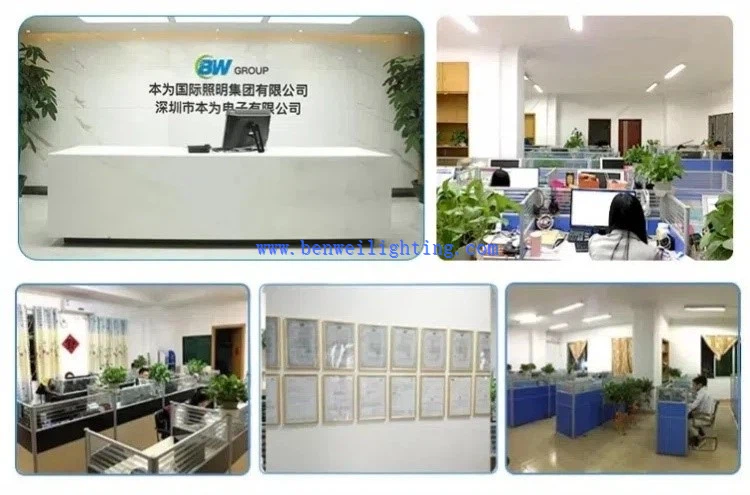
We are happy to have total control over the manufacturing process and the calibre of our products since we have our own facilities. Since we are producers rather than just brokers, we are dedicated to providing our customers with the best pricing. Since we are certain that the price and quality of our products are clear, we invite customers to see our samples first. Our commitment to quality and customer satisfaction drives us to continuously provide top-notch goods.
Our address
3rd Floor, 5th Building, Hebei Industrial Park, Hualian Community, Longhua District, Shenzhen, China