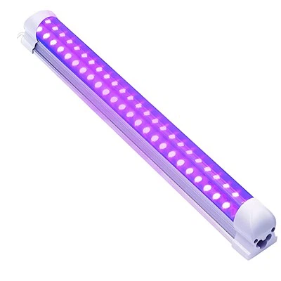
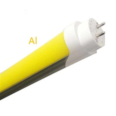
The integration of light-emitting diode (LED) tube lights into existing lighting infrastructure has raised significant technical inquiries regarding their interchangeability with conventional fluorescent tube fixtures. While LED tube lights offer superior energy efficiency, extended operational lifespan, and enhanced luminous efficacy, the question of whether they can be deployed universally across all fixture types requires a nuanced, multi‑parametric analysis. This paper systematically examines the critical factors governing LED tube light compatibility, including dimensional constraints, electrical characteristics, ballast dependencies, thermal management, and photometric requirements. The objective is to provide a rigorous framework for assessing fixture‑specific suitability, thereby mitigating safety hazards and performance degradation.

Dimensional Compatibility Parameters
Length Standards
LED tube lights are manufactured according to standardized lengths that correspond to traditional fluorescent tube sizes. The most common nominal lengths are 2 ft (∼600 mm), 4 ft (∼1200 mm), and 8 ft (∼2400 mm). However, actual physical lengths may vary by up to ±5 mm depending on the manufacturer. Fixture housings designed for fluorescent tubes often have fixed end‑cap spacing; any deviation can result in improper electrical contact, mechanical stress, or complete insertion failure. Therefore, precise measurement of the existing fixture's internal length is mandatory prior to replacement.
Diameter Specifications
Tube diameter is denoted by the T‑number, which represents eighths of an inch. Typical diameters include T5 (5/8 in ≈ 16 mm), T8 (1 in ≈ 25.4 mm), and T12 (1.5 in ≈ 38.1 mm). Although some LED tubes are designed with diameter adapters, mismatched diameters can cause insecure mounting, misalignment of the light distribution pattern, or interference with fixture reflectors. For example, installing a T12 LED tube into a T8‑only fixture is mechanically impossible without adapters, while a T8 tube in a T12 fixture may leave excessive clearance, leading to vibration‑induced contact failure.
Pin Configuration and Base Types
Most linear fluorescent fixtures employ G13 bi‑pin bases (for T8 and T12) or G5 bases (for T5). LED tube lights must have an identical pin spacing and base geometry to achieve electrical and mechanical mating. Non‑standard pin designs, such as single‑ended or double‑ended power feed configurations, further complicate compatibility. Consequently, dimensional conformance alone is insufficient; the pin arrangement must match both the fixture's lamp holders and the intended electrical pathway.
Electrical Compatibility Considerations
Input Voltage Ratings
LED tube lights are predominantly available in two nominal voltage classes: 120 V AC (typical for North American residential applications) and 277 V AC (common in commercial lighting systems). A voltage mismatch – for instance, operating a 120 V rated tube on a 277 V circuit – will almost certainly cause immediate driver failure, overheating, or arcing. Conversely, a 277 V tube on a 120 V supply may fail to illuminate or exhibit intermittent operation. Therefore, verifying the fixture's line voltage using a multimeter is a prerequisite for safe installation.
Ballast Compatibility Architectures
Type A LED tubes are engineered to operate directly with existing fluorescent ballasts – either magnetic (older) or electronic (newer). However, not all ballasts are compatible. Electronic ballasts that use high‑frequency (20 kHz – 100 kHz) square‑wave outputs may cause LED driver misreading, resulting in flicker, audible noise, or premature failure. Moreover, ballast compatibility lists provided by manufacturers must be strictly followed; using an unlisted ballast voids warranties and creates fire risks due to mismatched impedance.
Type B tubes require complete removal of the existing ballast, with line voltage (hot and neutral) wired directly to the lamp holders. This approach eliminates ballast‑induced losses and failure points but demands re‑wiring of the fixture. Common configurations include single‑ended power (both pins on one side carry line and neutral) or double‑ended power (one side line, the other side neutral). If the fixture is re‑wired incorrectly – for example, applying line voltage to both ends of a single‑ended tube – immediate short‑circuit and potential arc flash will occur. Only qualified personnel should perform such modifications.
A less common but increasingly prevalent architecture is Type C, which uses a dedicated external LED driver that replaces both the ballast and the internal tube driver. The tube itself contains only LED arrays; the driver is mounted remotely. While offering maximum efficiency and dimming capability, Type C systems are not interchangeable with Type A or B tubes. Fixture conversion to Type C requires new driver installation and low‑voltage wiring, making it a fixture‑specific solution rather than a universal retrofit.
Power Factor and Total Harmonic Distortion
LED tube lights exhibit different power factor (PF) and total harmonic distortion (THD) characteristics compared to fluorescent lamps. Low‑PF tubes (PF < 0.7) can cause nuisance tripping of circuit breakers in circuits shared with sensitive electronics. High THD (>20%) may lead to neutral conductor overheating in three‑phase systems. Existing fixtures not designed for such electrical signatures may experience relay chattering or contact welding in relay‑based lighting controllers.
Thermal and Safety Considerations
Heat Dissipation Requirements
Unlike fluorescent tubes that emit significant heat in the infrared spectrum, LED tubes generate heat at the junction level and require conduction via the tube's aluminum backplane. Many older fixtures are enclosed or have minimal airflow, trapping heat. Elevated ambient temperatures (>50 °C) inside a fixture can degrade the LED's phosphor, reduce lumen maintenance, or trigger thermal shutdown. Consequently, fixture ventilation must be evaluated, and tubes with integral heat sinking (e.g., finned aluminum extrusions) are recommended for fully enclosed luminaires.
End‑Cap Temperature Ratings
The plastic end‑caps of LED tubes are typically rated for a maximum operating temperature of 85 °C. In fixtures where the ballast (if retained) or nearby components radiate heat, end‑caps may exceed this rating, leading to embrittlement, cracking, and exposure of live pins. Infrared thermography should be employed post‑installation to verify that end‑cap temperatures remain within specification.
Electrical Safety and Grounding
When retrofitting Type B (ballast‑bypass) tubes, the fixture's ground continuity must be maintained. Many older fixtures use the ballast case as a grounding path; removing the ballast without re‑establishing a dedicated ground wire creates a shock hazard. Additionally, open‑circuit voltage during installation – if the fixture is mistakenly energized – can be lethal. Lockout/tagout procedures are mandatory for any wiring modification.
Photometric and Application Compatibility
Correlated Color Temperature (CCT) Selection
LED tube lights are available in CCTs ranging from 2200 K (extra warm) to 6500 K (daylight). The appropriate CCT is not a compatibility issue with the fixture itself but rather with the intended visual environment. However, mixing CCTs in a multi‑lamp fixture can produce objectionable color shifts due to different spectral power distributions. Moreover, fixtures with aged reflectors or lenses may cause color distortion; for example, a yellowed diffuser will shift a 5000 K tube toward 3500 K.
Color Rendering Index (CRI)
Standard fluorescent fixtures often deliver a CRI of 70–80. High‑quality LED tubes achieve CRI >90. While a higher CRI is generally beneficial, compatibility issues arise when a fixture's optical design (e.g., specular louvers) creates glare with a high‑CRI, high‑intensity source. Additionally, some photosensitive control systems (daylight harvesting sensors) calibrated for fluorescent spectra may misinterpret LED spectra, leading to erratic dimming or switching behavior.
Luminous Flux Distribution
LED tubes typically emit light over a narrower beam angle (∼120° to 160°) compared to fluorescent tubes (∼360° omnidirectional). A fixture designed to reflect light from the full circumference of a fluorescent tube may produce dark bands or uneven illumination when fitted with an LED tube. Therefore, compatibility includes photometric matching; fixtures with deep troffers or indirect lighting geometries may perform poorly with standard LED tubes, requiring purpose‑built "wide‑dispersion" LED tubes.
Regulatory and Code Compliance
UL and DLC Listings
In North America, LED tube lights must bear UL (Underwriters Laboratories) or ETL (Intertek) listing specifically for retrofit applications. A tube listed for "Type A" operation cannot be legally or safely used in a Type B rewired fixture. Similarly, the fixture itself, after modification (e.g., ballast removal), becomes a new electrical assembly that may require field labeling per NEC (National Electrical Code) Article 410.6. Failure to comply invalidates insurance coverage.
Energy Code Constraints (ASHRAE 90.1 / IECC)
Commercial retrofits must comply with lighting power density (LPD) limits. While LED tubes reduce wattage, replacing only the tubes while retaining inefficient ballasts (in Type A operation) may still violate LPD requirements if the ballast consumes 10–15 W beyond the tube's rating. Type B or C conversions are generally preferred for code compliance.
Conclusion
LED tube lights cannot be used indiscriminately in any lighting fixture. A systematic evaluation of four interdependent domains – dimensional fit (length, diameter, pin type), electrical compatibility (voltage, ballast architecture, power quality), thermal safety (heat dissipation, end‑cap temperatures, grounding), and photometric suitability (CCT, CRI, beam angle) – is essential. Furthermore, regulatory listings and local electrical codes impose binding constraints on retrofit methods. The universal answer is therefore negative: only fixtures that satisfy all the above criteria, after any necessary modifications (e.g., ballast bypass), can safely and effectively host LED tube lights. End users and lighting professionals must treat each fixture as a unique system, conducting compatibility verification per manufacturer datasheets and, where applicable, commissioning electrical measurements. Adherence to this protocol will yield the promised benefits of LED technology without compromising safety or performance.

How To Cooperate With Us?
Our firm prides itself on owning its own factory, guaranteeing complete control over the production process and the quality of our goods. We are not only agents; we are manufacturers committed to offering our clients the most competitive rates available. We invite consumers to evaluate our samples first, as we are assured that the quality and pricing of our items are self-evident. Our dedication to excellence and client satisfaction compels us to consistently perform at our best and provide superior quality products.
Our address
3rd Floor, 5th Building, Hebei Industrial Park, Hualian Community, Longhua District, Shenzhen, China