Introduction: The Light That Oscillates Without Being Seen
The human eye cannot see flicker above roughly 80 Hz. The visual cortex can. This discrepancy-between what the eye reports and what the nervous system registers-is the space in which most LED lighting operates, and it is the space in which the intelligent constant-current driver earns its significance.
Temporal light modulation (TLM) is the variation of light output over time. At frequencies below the conscious flicker threshold, it manifests as a visible stroboscopic effect or as the phantom array-a trail of ghost images that appears when the eye performs a saccade across a modulated source. At frequencies above that threshold, it becomes invisible to consciousness but not to physiology. Studies have documented that electronic ballasts raising the operating frequency of fluorescent lighting from 100 Hz to the 50–60 kHz range reduced headaches and eyestrain among office workers. The adverse effects attributed to TLM by the IEEE Power Electronics Society include fatigue, decreased performance, migraines, eyestrain, anxiety, vertigo, and headache. The light does not need to be seen flickering to produce these outcomes. It only needs to be modulated.
The driver is the component that determines whether an LED fixture modulates. The LED chip itself responds to current with near-instantaneous emission; its optical output is a direct, linear function of the forward current it receives. This is precisely why the driver's architecture matters so much. An LED driven by a clean, continuous current emits a clean, continuous light. An LED driven by a switching current emits a switching light, regardless of how well the emitter itself is manufactured.
This article proceeds in four movements. Section 2 establishes the physiological stakes and the standards that define them. Section 3 examines the two driver topologies that dominate the market-constant-voltage with PWM dimming and constant-current with closed-loop regulation-and explains why the former generates flicker by design while the latter suppresses it at the circuit level. Section 4 addresses the thermal contingency of flicker elimination: why a driver that performs cleanly at installation can degrade into a flickering one, and why the iron-clad base is the component that prevents that degradation. Section 5 concludes with the case for treating flicker-free operation as a system-level property rather than a driver specification.
The Physiological Stakes and the Standards That Define Them
Modulation Depth, Frequency, and the IEEE 1789 Threshold
The severity of TLM is a function of two variables: the frequency of the modulation and the depth of the modulation, expressed as percent flicker or modulation depth. IEEE 1789-2015 provides recommended limits for the relationship between the two. For frequencies between 90 Hz and 1,250 Hz, the low-risk level is defined as modulation depth not exceeding 0.08 times the frequency in hertz. At 120 Hz-the dominant flicker frequency in 60 Hz mains systems-this yields a low-risk threshold of 9.6%, rounded to 10%. The no-observable-effect level is defined as 0.0333 times the frequency, yielding 4% at 120 Hz.
These numbers establish the target. A driver that holds LED current modulation below 4% at 120 Hz is operating in a regime where the biological effects of flicker are, by the standard's definition, not observable. A driver that holds it below 9.6% is operating at low risk. A driver that operates at 30% modulation-a figure that has been proposed as a minimal compliance threshold in some energy code discussions-is delivering a light output that swings by nearly one-third of its average value, cycle after cycle, in direct contravention of the standard's intent.
Beyond Visible Flicker: The Phantom Array and the Stroboscopic Effect
The IEEE 1789 framework addresses the modulation that produces visible flicker and the sub-visible modulation that produces biological effects. It also implicitly touches on a third phenomenon that is particularly relevant to linear lighting: the phantom array. When the eye moves across a modulated source, the modulation frequency need not be low for the effect to appear. The phantom array can be perceived at modulation frequencies far above the flicker fusion threshold, and it is the reason why a fixture that appears steady when stared at directly can produce a trail of ghost images when the occupant scans a room.
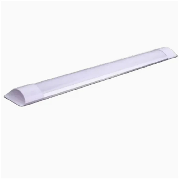
For a linear batten spanning a ceiling, the phantom array is a direct consequence of driver behavior. A PWM-driven LED batten is, electrically speaking, a source that is switching on and off at high frequency. The eye's saccades sample that switching pattern across space, and the visual system reconstructs it as a discontinuous trail. A constant-current driver, by contrast, holds the LED at a continuous current; there is no switching pattern to sample. The phantom array does not appear because the optical source is not, in fact, turning on and off.
The Regulatory Trajectory
The standards landscape is moving toward stricter flicker regulation. IEEE 1789-2015 is the reference point, but it is a recommended practice, not a mandatory requirement in most jurisdictions. The trajectory, however, is clear. As LED lighting has saturated residential and commercial markets, the health effects of TLM have moved from academic literature into procurement specifications and building codes. A fixture that cannot demonstrate modulation below the IEEE 1789 low-risk threshold is increasingly a fixture that cannot be specified for environments where occupants spend sustained time-which is to say, most environments that matter.
The driver is the component that determines whether a fixture meets this trajectory or is stranded by it.
The Driver Divide: Why Topology Determines Whether Flicker Exists at All
The PWM Constant-Voltage Architecture: Flicker as a Design Consequence
The most common driver architecture in low-cost LED fixtures is constant-voltage output paired with pulse-width modulation (PWM) for dimming. The constant-voltage driver holds the output voltage fixed; the LED current is set by a series resistor or by the LED module's own internal regulation. Dimming is achieved by switching the output on and off at high frequency and varying the duty cycle-the proportion of time the output is on versus off.
This is an efficient method of dimming in the sense that it avoids the resistive losses of linear current regulation. It is also, from the perspective of temporal light modulation, a method that generates flicker by construction. When the duty cycle is 50%, the LED is at full current for half the period and zero current for the other half. The modulation depth is 100%. The frequency may be high enough to render the flicker invisible to conscious perception, but the IEEE 1789 framework does not exempt invisible modulation. At a PWM frequency of 1.25 kHz, a 100% modulation depth is at the boundary of the low-risk level; below that frequency, it exceeds the threshold. At the frequencies commonly used in low-cost dimming circuits-often in the low kilohertz or even hundreds of hertz-a PWM-driven LED operates well outside the recommended envelope.
The practical consequence is that a constant-voltage PWM driver can produce a fixture that looks perfectly steady to the eye while delivering a light output that oscillates between full intensity and zero. The occupant does not see the flicker. The nervous system registers it nonetheless.
The Constant-Current Alternative: Regulating the Variable That Determines Light
The LED is a current-driven device. Its luminous output is proportional to the forward current passing through the junction, and that relationship is the lever that a constant-current driver uses to control light. A constant-current driver does not hold voltage fixed and switch the output; it regulates the current itself, continuously and in closed loop, so that the LED receives a steady, defined current regardless of variations in input voltage or in the LED's own temperature-dependent impedance.
The mechanism is negative feedback. A sensing element-typically a resistor in series with the LED string-converts the LED current into a voltage signal. That signal is compared against a reference, and the error is used to adjust the switching element that controls power delivery to the LED. If the current rises above the target, the switch reduces the energy transfer; if it falls below, the switch increases it. The loop operates continuously, at a bandwidth far higher than the frequencies at which flicker becomes biologically relevant.
The result, at the optical level, is a current waveform that is not switched between zero and full value but held near a constant average with a small, high-frequency ripple superimposed upon it. The magnitude of that ripple is the variable that determines whether the driver is flicker-free in practice. A well-designed constant-current driver suppresses the ripple to a level that produces modulation depth below the IEEE 1789 no-observable-effect threshold. The light output follows the current: a steady current produces a steady light.
The Ripple Reduction Mechanism: From "Low Flicker" to "Near-Zero Modulation"
The distinction between a constant-current driver that reduces flicker and one that eliminates it lies in the ripple reduction circuitry. Patent literature in this domain describes the mechanism with precision. A current ripple reducing unit is placed in series with the LED load, incorporating a negative feedback control loop that forces the peak of the output current to approach its average value. The result, as described in the patent, is that "the ripple of the output current decreases to nearly zero," and in that condition, "the flicker effect is therefore eliminated".
This is the circuit-level meaning of "completely." It does not mean that the current is mathematically perfect; it means that the residual ripple is suppressed to a level below the threshold at which the light output produces any measurable or observable temporal light modulation. The IEEE 1789 no-observable-effect level at 120 Hz is 4% modulation. A driver that holds output current ripple to a level producing less than 4% modulation is, by the standard's own definition, operating in a regime where the biological effects of flicker are not observable. "Completely" is a statement about the relationship between the driver's output and the threshold of physiological consequence, not a claim of infinite precision.
The empirical record supports the principle. Research on LED driving conditions has shown that when an LED is driven by a linear constant-current source, its optical output exhibits no flicker phenomenon and appears as a smooth, straight line, precisely because the light output directly follows the current and the current is not being switched. The LED does not introduce flicker on its own. The driver either supplies a current that varies, in which case the light varies, or it supplies a current that is held steady, in which case the light is steady.
Constant-Current Regulation and the Avoidance of Unintended Modulation
There is a further advantage to constant-current architecture that is less discussed but equally consequential. A constant-voltage driver that relies on PWM for dimming is not the only source of flicker; a poorly regulated constant-voltage driver can also produce modulation when the input AC waveform couples into the output, when the load current changes abruptly, or when the driver's control loop becomes unstable. The constant-current architecture, by regulating the variable that directly determines light output, closes off these pathways. The driver is not managing a proxy for light output; it is managing light output itself, through the current that produces it.
This is why the constant-current driver's flicker performance is not an add-on specification but a structural consequence of its control objective. A driver designed to hold current steady is a driver designed to hold light steady. The two are not separable.
The Thermal Contingency: Why Flicker Elimination Must Be Sustained, Not Merely Achieved
The Electrolytic Capacitor as the Driver's Temporal Weak Point
A constant-current driver's ability to suppress ripple depends on the integrity of its energy storage and filtering components, and the most vulnerable of these is the electrolytic capacitor. The capacitor's function is to absorb the high-frequency ripple current that the switching converter generates, providing instantaneous energy storage so that the LED sees a smoothed current rather than the raw switching waveform. As the capacitor degrades, its capacitance falls and its equivalent series resistance rises. The filtering becomes less effective. The ripple that reaches the LED increases.
The degradation mechanism is thermal. The effective operating life of an electrolytic capacitor is strongly dependent on ambient temperature and on the internal temperature rise produced by ripple current flowing through its internal impedance. A commonly cited engineering relationship holds that capacitor life doubles for every 10°C reduction in operating temperature. A capacitor rated for 8,000 hours at 105°C will last approximately 16,000 hours at 95°C, 32,000 hours at 85°C, and 64,000 hours at 75°C. The driver's thermal environment therefore determines how long it can maintain the ripple suppression that produces flicker-free operation.
This is the point at which flicker elimination ceases to be a circuit design question and becomes a fixture architecture question. A driver that suppresses ripple perfectly at 25°C may lose that suppression as its capacitors age under thermal stress. The light does not flicker on the first day. It begins to flicker when the driver's filtering capability has degraded to the point where the residual ripple crosses the modulation threshold.
The Iron-Clad Base as the Driver's Thermal Guardian
The iron-clad base addresses this degradation pathway at its source. Iron conducts heat away from the driver enclosure and spreads it across a larger surface area for dissipation to the ambient air. By limiting the temperature rise within the fixture, the base keeps the driver's electrolytic capacitors within a thermal envelope in which their degradation rate is minimized and their filtering capability is preserved across the fixture's service life.
The consequence for flicker is direct. The driver's ripple suppression is a function of its capacitors' health. The capacitors' health is a function of their operating temperature. The operating temperature is a function of the fixture's thermal architecture. The iron-clad base is the component that closes this chain. A fixture with a constant-current driver but an inadequate thermal pathway is a fixture that delivers flicker-free light for as long as its capacitors remain within tolerance-and then begins to flicker as they age. A fixture with both the driver and the thermal base is a fixture whose flicker-free claim is not time-limited by thermal degradation.
The System-Level Claim
The complete elimination of flicker is therefore a system-level property, not a component specification. It requires:
A driver architecture that regulates current rather than voltage, so that the light output is controlled at its source rather than through switching.
A ripple reduction mechanism that suppresses the residual modulation to below the IEEE 1789 no-observable-effect threshold, converting a "low-flicker" design into a genuinely flicker-free one.
A thermal pathway that preserves the driver's filtering capability across tens of thousands of hours, so that the elimination achieved at installation is not eroded by capacitor degradation.
The intelligent constant-current driver supplies the first two. The iron-clad base supplies the third. The combination is what makes "completely" a description of the product's behavior over time rather than a description of its performance on the day it was tested.
Conclusion: The Driver Is the Difference Between Light and Lighting
The LED emitter is a remarkable device. It converts current to photons with an efficiency that incandescent and fluorescent sources cannot approach, and it does so without mercury, without a fragile glass envelope, and without the thermal inertia that makes filament and discharge sources slow to respond. But the emitter is not a light fixture. It is a component that produces light when-and only when-it receives a current that is suitable for its operation.
The driver determines what kind of current that is. A constant-voltage PWM driver supplies a current that switches between zero and full value, and the LED produces a light that does the same. The switching may be fast enough to escape conscious detection, but it does not escape the IEEE 1789 framework, and it does not escape the nervous system that registers modulation even when the eye does not report it. A constant-current driver with negative-feedback ripple reduction supplies a current that is held steady, and the LED produces a light that is steady in the same measure. The residual ripple is suppressed to a level below the threshold of physiological consequence. The light does not flicker because the current does not flicker, and the current does not flicker because the driver is designed to prevent it.
The thermal architecture determines whether that prevention endures. A driver is an electronic assembly, and its precision is contingent on the health of its components. The iron-clad base is the component that keeps the driver within its thermal design envelope, preserving the capacitor integrity on which ripple suppression depends. The combination-constant-current driver and iron-clad base-is the physical basis of the claim that flicker is eliminated not merely at the factory but across the fixture's service life.
For the occupant, the consequence is not a feature to be noticed. It is the absence of something that should never have been present: the invisible oscillation that fatigues the eye, fragments the moving gaze, and taxes the visual cortex across hours of occupancy. The intelligent constant-current driver does not make the light brighter or more efficient. It makes the light still. That stillness is the quality on which every other quality of a lighting installation depends, and it is the reason the driver-not the emitter-is the component that separates a light source from a light worth living beneath.
How To Cooperate With Us?
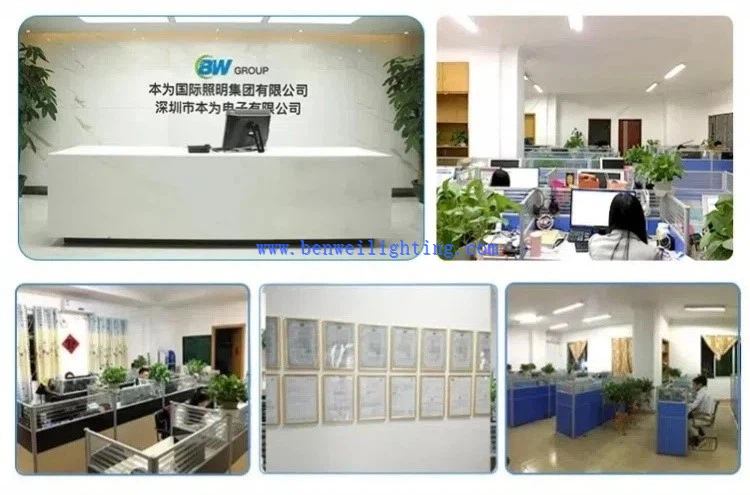
We are happy to have total control over the manufacturing process and the calibre of our products since we have our own facilities. Since we are producers rather than just brokers, we are dedicated to providing our customers with the best pricing. Since we are certain that the price and quality of our products are clear, we invite customers to see our samples first. Our commitment to quality and customer satisfaction drives us to continuously provide top-notch goods.
Our address
3rd Floor, 5th Building, Hebei Industrial Park, Hualian Community, Longhua District, Shenzhen, China