Facility managers, warehouse operators, and industrial engineers face a critical decision when upgrading overhead lighting: which high‑bay luminaire delivers the optimal balance of luminance, longevity, and lifecycle cost? The market offers dozens of UFO‑style LED high bays, but not all are created equal. Selecting the wrong fixture leads to uneven illumination, premature driver failure, and wasted energy. This guide provides a systematic, engineering‑driven methodology to choose the right UFO LED high bay for your specific facility. Drawing on photometric principles, thermal management analysis, and real‑world installation practices-including core technologies such as advanced chip integration, dual mounting brackets (disc and U‑shaped), and precision optics-we equip you with the knowledge to make a confident, future‑proof investment.
Introduction: The High‑Bay Imperative
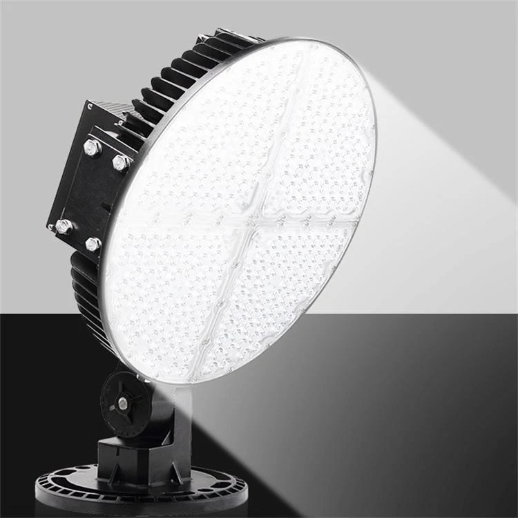
The flying-saucer-like look of UFO LED high bays causes them to be referred to as low-profile luminaires that are circular in shape. Warehouses, gymnasiums, factory halls, and cold storage facilities are examples of high-ceiling settings that they dominate ranging from six metres to twenty metres in height. When compared to conventional metal halide or fluorescent high bays, LED ultra-fast-on (UFO) lights provide instant-on lighting, energy savings of between 50 and 70 percent, and lifespans of more than 50,000 hours. On the other hand, the rise of low-quality items, such as counterfeit chips, undersized heat sinks, and flimsy brackets, has made choosing very difficult. A well-designed UFO high bay combines three features that cannot be compromised: quality LED chips (for example, from tier-one foundries), a strong thermal route (die-cast aluminium housing), and adaptable mounting accessories (with a disc bracket for flat ceilings and a U-shaped bracket for truss or pendant installation). This guide will break down each selection criteria, explain the technologies that are underpinning it, and provide specifics on the advantages of a well chosen fixture. By doing so, your establishment will be able to reach ideal lux levels while incurring the lowest possible total cost of ownership.
How to Choose the Correct UFO LED High Bay
Selecting a UFO high bay requires answering five interdependent questions: mounting height, required illuminance, beam angle, environmental conditions, and control compatibility.
Determine Mounting Height and Spacing
The inverse‑square law governs light intensity: doubling the distance quarter the illuminance. For a given fixture lumen output, mounting height dictates the spacing between units.
| Ceiling Height | Recommended Fixture Power (typical) | Max Spacing (centre‑to‑centre) |
|---|---|---|
| 6 – 8 m | 100 – 150 W | 4 – 5 m |
| 8 – 12 m | 150 – 240 W | 5 – 7 m |
| 12 – 16 m | 240 – 320 W | 7 – 9 m |
| 16 – 20 m | 320 – 500 W | 9 – 12 m |
Use a lighting design software (e.g., Dialux) with the fixture's IES file to simulate uniformity. Aim for a uniformity ratio (average illuminance / minimum illuminance) ≥0.6 for general industrial tasks, ≥0.7 for detailed assembly.
Match Beam Angle to Aisle Width and Column Spacing
UFO high bays typically offer three beam angle families:
60°–90° (narrow): For high‑bay warehouses with narrow aisles (≤3 m width). Concentrates light downward, minimising wall loss.
100°–110° (medium): The most versatile, suitable for open manufacturing areas, gymnasiums, and retail spaces.
120°–140° (wide): For low‑medium mounting heights (6–8 m) or wide‑open areas where even spread is critical.
If your facility has obstructed aisles (shelving, mezzanines), combine narrow‑beam fixtures above aisles and wide‑beam fixtures in cross‑aisles.
Evaluate Environmental Ratings (IP and IK)
Industrial environments present dust, moisture, vibration, and impact risks.
IP rating: Minimum IP65 for dusty environments (e.g., grain handling, cement plants). IP66 for washdown areas (food processing, car washes). IP54 for covered warehouses with low dust.
IK rating: IK08 (5 J impact resistance) for general industrial; IK10 (20 J) for high‑risk zones like sports halls with stray balls or heavy maintenance areas.
The product's die‑cast aluminium housing combined with silicone gaskets typically achieves IP65–IP66 and IK08–IK10.
Select Correlated Colour Temperature (CCT)
CCT affects visual acuity, safety, and worker circadian rhythms.
3000K–3500K (warm): Rare in industrial high bays; used in hospitality or retail contexts.
4000K (neutral white): Best for general manufacturing, warehouses, and logistics. Provides high contrast without excessive blue.
5000K–5700K (cool daylight): Preferred for detailed inspection, automotive repair bays, and facilities requiring alertness (24/7 operations). Note that above 5000K, some workers report glare; use diffused optics.
For multi‑shift facilities, consider tunable‑white or dual‑CCT modules (not available in all UFOs, but selectable drivers are emerging).
Verify Chip Quality and Lumen Maintenance
The LED chip is the heart of the fixture. Premium chips (e.g., from leading global foundries) guarantee high initial lumens per watt (≥150 lm/W at 85°C) and L70 >50,000 hours. Counterfeit chips often fail within 5,000 hours. To verify:
Request an LM‑80 report (lumen maintenance) and TM‑21 extrapolation. Look for L70 ≥ 54,000 hours at 85°C case temperature.
Check for real‑time thermal protection: the driver should reduce current automatically when the heat sink exceeds 90°C.
Assess Mounting Bracket Compatibility
Two bracket types are standard, and the correct choice simplifies installation and aiming:
Disc bracket (fixed): A flat, circular plate that mounts directly to a flat ceiling or junction box. Best for smooth concrete or drywall ceilings where the fixture will hang vertically without angle adjustment.
U‑shaped bracket (adjustable): A swivelling yoke that allows ±90° tilt (or more) and 360° rotation. Essential for sloped ceilings (e.g., sawtooth roofs), truss mounting, or wall‑mount applications where the beam must be aimed horizontally. Also used for pendant mounting on chains or cables.
Always confirm that the bracket is constructed from corrosion‑resistant steel or aluminium and supports at least 3× the fixture weight.
Core Technologies of the UFO LED High Bay
A superior UFO high bay integrates seven interdependent technologies, many of which are evident in the product described (disc & U‑shaped brackets, high‑grade chips, optimised housing).
High‑Density, Premium LED Chip Array
Instead of a few large‑power LEDs, quality UFOs use multiple mid‑power or high‑power chips arranged in a circular array. This improves thermal spreading and light uniformity. The chips are sourced from tier‑1 manufacturers (e.g., leading Korean or US foundries) with typical efficacy 160–180 lm/W at board level. The product's reference to "brand chip" confirms that no generic or re‑marked dies are used. Each chip is individually binned for colour consistency (SDCM ≤3), eliminating the patchy yellow/blue spots seen in cheap arrays.
Die‑Cast Aluminium Heat Sink with Finned Geometry
Thermal management determines LED lifespan. The UFO housing is typically made of die‑cast aluminium (e.g., ADC12) with an integrated fin array. The fins increase surface area for convective cooling. Compared to extruded aluminium, die‑casting allows complex curved shapes that maximise airflow while reducing weight. A properly designed heat sink keeps the LED junction temperature ≤85°C at 35°C ambient, achieving L70 >50,000 hours. The product's body (SAHUNG in source images, but unnamed here) uses thickened aluminium walls, preventing deformation under thermal cycling.
High‑Efficiency Constant Current Driver
The driver converts AC mains (100–277 V or 347 V) to regulated DC current. Essential features:
Constant current mode (e.g., 700 mA – 1.4 A) with over‑voltage, over‑current, and short‑circuit protection.
Power factor ≥0.95 and THD ≤15% to avoid harmonic pollution.
Surge protection (6 kV / 4 kA minimum; 10 kV for lightning‑prone regions).
Dimming compatibility (0–10 V, DALI, or PWM) for motion sensor integration.
The driver should be potted (encapsulated) for moisture and vibration resistance.
Optical Lens Design (PMMA or PC)
A secondary optical lens sits directly over the LED array. Precision‑moulded from optical‑grade polycarbonate (PC) or PMMA, the lens defines the beam angle (60°/90°/120°). High‑quality lenses feature TIR (total internal reflection) geometry, capturing stray light and directing it forward. This achieves up to 95% optical efficiency. Cheap lenses waste 15–20% of light as glare. The product's lens is typically UV‑stabilised, yellowing‑resistant, and rated for outdoor use.
Dual Bracket System for Versatile Installation
Disc bracket: A low‑profile circular plate pre‑drilled with slots for 4‑inch or 3.5‑inch junction boxes. The UFO housing attaches via three or four screws. This bracket offers zero adjustability but a clean, flush appearance.
U‑shaped bracket: A heavy‑gauge steel or aluminium yoke that attaches to the fixture via side trunnions. The yoke includes a central hole for a pendant hook, chain, or threaded rod. Tilt adjustment is secured by locking bolts. This bracket allows the fixture to be aimed precisely at workbenches, assembly lines, or sloped ceilings.
Some models offer both brackets in the box; others let you choose. For new construction, the disc bracket is simpler; for retrofit where existing hook mounts are present, the U‑shaped bracket is indispensable.
Environmental Sealing (IP65+)
A complete silicone gasket runs between the lens and housing, and another seals the driver compartment. All cable entries use IP68‑rated waterproof glands. This design prevents dust ingestion and resists high‑pressure water jets (IP66) or temporary immersion (IP67). The product achieves IP65 as a minimum, suitable for covered sheds; optional IP67 is available for food plants.
Optional Emergency Battery Backup
For facilities requiring egress lighting (OSHA, IBC), the UFO can integrate an emergency battery module that powers the LEDs at reduced output (e.g., 3 W or 10% of full) for 90 minutes during a blackout. This avoids separate emergency light fixtures.
Benefits of Using This UFO LED High Bay
Adopting a correctly specified UFO high bay yields quantifiable advantages across financial, operational, and safety domains.
Energy Savings of 60–75% vs. HID
A 250 W metal halide high bay consumes ~300 W (including ballast losses) and produces ≈22,500 initial lumens, which degrades to 12,000 lumens by mid‑life. A 150 W UFO LED high bay produces ≈24,000 lumens (160 lm/W) with no degradation >90% lumen maintenance at 50,000 h. Replacing 100 metal halide fixtures saves approximately 15,000 kWh per year – at 0.12/kWh,0.12/kWh,1,800 annually. With utility rebates, payback often under 18 months.
Extended Lifespan and Reduced Maintenance
Metal halide lamps require replacement every 15,000–20,000 hours; ballasts every 30,000 hours. UFO LED high bays operate for 50,000–100,000 hours (11–22 years at 12 h/day). Maintenance labour – renting a scissor lift, sending a crew – costs $200–500 per fixture change. Eliminating 5–10 changes over a decade saves tens of thousands of dollars per facility.
Instant On, Flicker‑Free, and No Restrike Delay
Unlike HID lamps that need 5–15 minutes to warm up and cool down before restrike, UFO LEDs reach full brightness instantly (≤0.5 s). This is critical for motion‑sensor areas (warehouse zones that are only activated when a forklift approaches). Flicker‑free constant current drivers prevent the strobe effect that can cause machinery‑operator optical confusion.
Superior Colour Rendering (CRI ≥80)
Most industrial LEDs achieve CRI 80–85, compared to CRI 65 for metal halide and CRI 50 for high‑pressure sodium. This improves colour discrimination for safety signs, product labelling, and inventory picking accuracy. High CRI also reduces eye strain during 8‑hour shifts.
Low Glare and Uniform Illumination
The combination of a wide‑beam‑angle secondary lens (120°) and a deep‑set LED array reduces direct glare. When coupled with the U‑shaped bracket allowing angled mounting, you can position fixtures to avoid shining directly into workers' eyes. Uniformity improves safety (fewer dark corners where accidents occur) and worker morale.
Flexible Mounting for Any Ceiling Type
The disc bracket simplifies installation on flat concrete ceilings – drill four holes, anchor, screw on the fixture. The U‑shaped bracket handles sloped roofs (e.g., 15° pitch) by tilting the fixture to vertical orientation, maintaining proper light distribution. It also allows mounting on I‑beams using beam clamps, or hanging at custom heights using chains. One product covers all scenarios.
Environmental Compliance and Rebates
LED high bays contain no mercury (unlike metal halide or fluorescent). They qualify for ENERGY STAR, DLC (DesignLights Consortium) premium tier, and utility rebates. Using a DLC‑listed fixture can reduce upfront cost by 50–50–150 per fixture through direct incentives.
Correct Usage Scenarios and Installation Methods
To realise the benefits, deploy the UFO LED high bay in appropriate settings and follow professional installation protocols.
Ideal Use Scenarios by Facility Type
| Facility Type | Recommended Power | Beam Angle | Mounting Bracket | Special Notes |
|---|---|---|---|---|
| Warehouse (rack aisles) | 150–240 W | 60°–90° (narrow) | U‑shaped (pendant) | Position above aisles, not racks |
| Open manufacturing floor | 150–200 W | 100°–120° | Disc or U‑shaped | Use 5000K for high alertness |
| Cold storage (≤ -20°C) | 200–300 W | 120° | Disc (sealed) | Ensure rated for low temp (special driver) |
| Gymnasium / sports hall | 240–320 W | 120° | U‑shaped (chain) | IK10 rating and wire guards against ball impact |
| Car dealership showroom | 100–150 W | 110° | Disc | 4000K, CRI ≥90 for vehicle paint accuracy |
| Food processing washdown | 150–200 W | 120° | U‑shaped | IP66, stainless steel brackets |
| Retail big‑box store | 150–240 W | 120° | Disc | Incorporate daylight harvesting sensors |
Installation Steps for Disc Bracket (Flat Ceiling)
Safety: Disconnect circuit power. Use a lift appropriate for ceiling height.
Mount bracket: Position the disc bracket on the ceiling surface. Mark four drill points through the slotted holes. Use a rotary hammer to drill anchor holes (concrete) or self‑tapping screws for steel purlins. Secure bracket with M8 or M10 anchors.
Make electrical connections: Pull supply cable (3‑core, 12–14 AWG) through the bracket's centre hole. Connect to the fixture's terminal block or to the driver input leads: line (black), neutral (white), earth (green/yellow). If dimming, connect additional 0–10V wires (purple/grey). Use waterproof wire nuts or lever connectors.
Attach fixture to bracket: Align the UFO's mounting holes with the disc bracket's threaded inserts. Secure with the provided screws (typically three or four). Torque to 2 N·m. Ensure the silicone gasket between fixture and bracket is seated.
Power on and test: Restore power. Verify illumination and, if dimming, adjust to desired level. Use a lux meter to confirm uniformity.
Installation Steps for U‑Shaped Bracket (Sloped Ceiling or Pendant)
Assemble bracket to fixture: Attach the U‑shaped yoke to the fixture's side trunnions using the provided pivot bolts. Do not fully tighten; allow tilting.
Hang the assembly: If using chains: attach chains to the hook points on top of the yoke. Secure chains to ceiling anchors (eye bolts, beam clamps, or unistrut). Adjust chain length to achieve desired mounting height. Ensure chains are level.
For rigid pendant: Thread a 3/8″ or 1/2″ threaded rod through the yoke's top centre hole. Secure with washers and nuts above and below the yoke.
Electrical connection: Route the supply cable along the chain (using cable ties) or through the centre of the threaded rod. Connect to the fixture as above. If using a waterproof cord grip, ensure the gland is tightened.
Aim the fixture: Loosen the side pivot bolts, tilt the fixture to the required angle (e.g., 15° for a sloped ceiling to bring the beam perpendicular to the floor). Tighten bolts to 8–10 N·m. For wall‑mount applications, tilt 90° to fire horizontally.
Final testing: Power on. Verify that the beam covers the intended area without bright spots or dark zones.
Common Mistakes to Avoid
Under‑specifying power: Using 150W at 15 m height results in <50 lux. Always simulate or use the conservative rule: required lumens = (target lux) × (area m²) × (1.2 loss factor).
Ignoring ambient temperature: Standard UFOs work from -30°C to +50°C. For freezers (-40°C), request low‑temperature driver with cold‑start capability.
Incorrect bracket choice: Using a disc bracket on a 10° sloped ceiling will tilt the fixture relative to gravity, casting light unevenly. Use U‑shaped bracket and level the fixture.
Forgetting surge protection: In industrial zones with heavy motors or lightning risk, add an external SPD (Type 2) even if the driver has built‑in protection.
No thermal gap: The heat sink needs air circulation. Do not mount the disc bracket flush against a solid ceiling without standoffs; leave at least 2 cm clearance for airflow.
Maintenance Protocol
Every 6 months: Clean the lens with isopropyl alcohol and a microfiber cloth. Check for insect ingress (seals can degrade).
Every 12 months: Measure light output with a portable lux meter at floor level; compare to initial baseline. If output has dropped >20%, inspect driver or LED board.
If flicker occurs: Test with a different driver (modular driver replacements are available on some UFOs). If not modular, replace the whole fixture under warranty.
Re‑torque mounting bolts after the first thermal cycles (30 days of operation).
Conclusion
Selecting the right UFO LED high bay is a systematic process that balances mounting height, beam angle, environmental protection, and thermal integrity. The ideal fixture combines premium LED chips, a die‑cast aluminium heat sink, a high‑efficiency constant current driver, and versatile brackets – disc bracket for flat ceilings, U‑shaped bracket for sloped or pendant mounting. By following this guide, you will avoid the pitfalls of underperformance, premature failure, and hidden maintenance costs. A correctly specified UFO high bay delivers 60–75% energy savings, 50,000–100,000 hours of maintenance‑free operation, and a safer, more productive work environment. Whether you manage a warehouse, factory, gym, or cold store, invest in a high bay designed for the real world – because cutting corners on light cuts corners on safety and savings.

How To Cooperate With Us?
Our firm prides itself on owning its own factory, guaranteeing complete control over the production process and the quality of our goods. We are not only agents; we are manufacturers committed to offering our clients the most competitive rates available. We invite consumers to evaluate our samples first, as we are assured that the quality and pricing of our items are self-evident. Our dedication to excellence and client satisfaction compels us to consistently perform at our best and provide superior quality products.
Our address
3rd Floor, 5th Building, Hebei Industrial Park, Hualian Community, Longhua District, Shenzhen, China