Introduction: Why "Bright" Is the Wrong Question
The Specification-Sheet Illusion
A high-wattage LED bulb can be specified into a commercial or residential fixture on the strength of two numbers: wattage equivalent and initial lumens. Both numbers are true at the moment of measurement. Neither number describes what the bulb will do after 5,000, 10,000, or 25,000 hours of operation. The specification-sheet illusion is the gap between the initial performance a buyer sees and the maintained performance the installation actually receives.
That gap is not hypothetical. LED lumen depreciation is driven primarily by heat at the junction, and the thermal path from junction to ambient is the narrowest and most compromised part of a compact E27 form factor. A bulb that produces a high initial lumen number without a deliberate thermal strategy will depreciate faster than its specification suggests, shift color as its phosphor degrades, and fail at the driver level before the LED chips themselves have reached the end of their useful life. The teardown below examines the components that determine which trajectory a given bulb follows.
The Three Subsystems That Define a High-Wattage E27 Bulb
Disassembly of the product reveals three functional domains. The thermal domain consists of the aluminum fin heat sink and the integrated fan, whose joint task is to move heat from the LED board and driver to the ambient air. The electrical domain consists of the IC constant-current driver, whose task is to deliver stable current to the LED array while protecting itself from the thermal and electrical stresses of continuous duty. The optical domain consists of the high-transmittance PC mask, whose task is to convert the LED array's point-source emission into soft, uniform light without absorbing a disproportionate share of the lumens.
Each domain has a failure mode. The thermal domain fails when junction temperature rises above its design window. The electrical domain fails when the driver's electrolytic capacitor dries out or its current regulation degrades. The optical domain fails when the PC mask yellows or loses transmittance under sustained heat. A bulb is only as good as the weakest of these three domains, and the teardown shows how the product's architecture attempts to align them rather than optimize one at the expense of the others.
The Teardown Logic
This article proceeds in the order of the physical stack: heat path first, because every other component lives or dies by it; driver second, because it is the subsystem most likely to fail prematurely; optics third, because the diffuser is the component the user actually sees. The final section connects the three domains to the purchasing decision, arguing that the presence of a fan and an IC driver is not a feature list but a statement about which failure modes the product was engineered to resist.
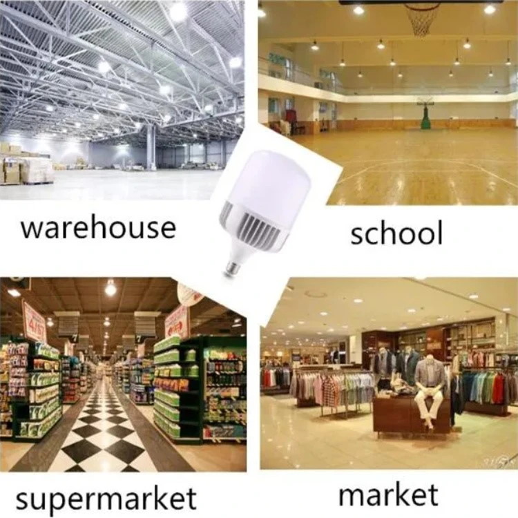
The Thermal Stack: Why a Fan Is the Difference Between "Bright" and "Still Bright"
The Junction Temperature Problem in a Compact Form Factor
An LED converts electricity into two outputs: photons that leave the package and heat that must be conducted away from the junction. In a low-power A60 bulb, the heat flux density is modest, and a passive aluminum heat sink can dissipate it by natural convection. In a high-wattage E27 bulb, power is packed into the same screw-in envelope, and the heat flux density rises accordingly. If the heat is not removed fast enough, the junction temperature rises, and every degradation mechanism in the device accelerates.
The engineering literature states the relationship bluntly. A classic rule of semiconductor reliability holds that every 10°C increase in operating temperature roughly halves a device's useful life. A chip running 20°C hotter than its design target can age approximately four times faster than one held within its thermal window. This is not a marginal effect. It is the difference between a bulb that meets its rated service life and one that becomes a maintenance line item within two to three years.
Passive Fins Alone Hit a Wall at High Wattage
The product's aluminum fin heat sink is the first stage of thermal management. Aluminum's thermal conductivity spreads heat from the localized LED hot spots across a larger surface area, and the finned geometry increases the area available for convective transfer to the air. This is the same thermal strategy used in specification-grade commercial luminaires.
But passive finning has a physical ceiling in a compact bulb. National Academies assessment of solid-state lighting states the constraint directly: "higher power LED lighting products (1,500 lumens and above) pose significant thermal management challenges. Passive heat sinks are not sufficient to keep the LED junction sufficiently cool. Therefore, to achieve desired lumen values in a small form factor… active cooling may be required to dissipate the heat." The same logic is confirmed in the product-specific literature: passive cooling "works well up to roughly 15 or 20 watts," but at 30, 50, or more watts, "the heat sink would have to become impractically large and heavy, which is incompatible with an E27 screw socket rated for a compact bulb."
The fin stack is therefore necessary but not sufficient. It manages the conductive and spreading portion of the thermal path. It does not, on its own, move enough heat out of the bulb to sustain high output in continuous duty.
The Fan as the Convective Multiplier
The built-in fan changes the convective term. Forced convection across the fin surfaces increases the heat-transfer coefficient by a factor of two to five compared with natural convection, depending on airflow velocity and fin geometry. This is the engineering rationale for active cooling in high-output socket-type lamps: the fan does not replace the heat sink; it makes the heat sink function at the wattage the bulb was designed to deliver.
The performance data for fan-cooled high-wattage E27 bulbs supports the architecture. A fan-cooled high-wattage E27 T-bulb is rated to keep light decay under 30% even after 25,000 working hours-a lumen-maintenance figure that is difficult to achieve with passive cooling alone at comparable wattage. The fan buys thermal headroom, and that headroom is what allows the "bright" claim to remain true after the first year of operation.
The Fan's Own Life: Bearing Choice and the Weak-Link Question
A fan introduces a moving part into a device that would otherwise have none, and moving parts raise the question of the fan becoming the new weak link. The engineering literature acknowledges this concern: mechanical fans have been used in high-power LED products, but they are "not desirable for many reasons, including short life, acoustic noise, attraction of dust, and increased energy use." The reliability of the fan therefore depends on the bearing technology and the control strategy.
Fan bearing life is specified as L10 life-the number of hours at which 90% of a population of fans will still be operating. Published ranges place sleeve bearings at roughly 30,000–40,000 hours L10, and ball bearings at 50,000–100,000 hours or more. Sealed sleeve and hydraulic bearing systems can reach 50,000 hours L10 at 40°C. For a bulb rated at tens of thousands of hours of LED life, the fan bearing is a specification that deserves scrutiny: a fan rated at 30,000 hours L10 is not mismatched to an LED rated at 25,000 hours, but a fan rated at 50,000 hours L10 provides a wider reliability margin.
The product's fan operates within a thermal control context. PWM speed regulation based on the LED lamp's temperature state is a known technique for reducing dust accumulation and ensuring the fan operates only when thermal conditions require it, which extends fan life and reduces acoustic noise. The presence of a thermally controlled fan is therefore a more meaningful specification than the mere presence of a fan: it indicates that the cooling system is designed to manage its own duty cycle rather than running at full speed continuously.
What the Fan Cools Besides the LEDs
The thermal stack is not only about the LED chips. The fan moves air across the fin structure that sits adjacent to the driver compartment, and that airflow cools the entire electronic assembly. Heat attacks the bulb along multiple fronts: the LED chip, the phosphor layer, the solder joints and wire bonds, the electrolytic capacitors inside the driver, and the PC cover. The fan's contribution is system-level: it reduces the temperature of every component that shares the thermal envelope, which is why the teardown of a fan-cooled bulb is a teardown of the whole reliability strategy, not just the light source.
The IC Driver: Protecting the Subsystem That Fails First
Why the Driver, Not the LED, Determines Service Life
The LED chip is often described as the long-life component, and that description is accurate in isolation. But a bulb is a system, and the system's life is determined by its weakest element. In many high-output LED bulbs, the weakest element is the driver-specifically, the aluminum electrolytic capacitor on the DC bus.
Field failure analysis of LED drivers is consistent on this point. In a documented batch of industrial LED fixtures that began flickering and failing within two to three years of installation, teardown of the failed drivers showed the LED chips were intact; the failure was localized to the electrolytic capacitor, which had bulged, lost roughly 60% of its capacitance, and risen in equivalent series resistance. The LED's rated life of 50,000 hours describes the chip's lumen depreciation, not the driver's survival. The driver's life is set by its weakest component, and in most designs that component is the electrolytic capacitor. A capacitor rated at 105°C and 8,000 hours can define the upper bound of the entire system's service life long before the LED chip approaches its rated depreciation point.
The Constant-Current Function: Why It Is Non-Negotiable
An LED is a current-driven device. Its forward voltage drops as junction temperature rises-typically by about 2 mV per °C. If an LED is driven by a constant-voltage source, the negative temperature coefficient creates a positive feedback loop: higher temperature lowers forward voltage, which draws more current, which raises power dissipation and temperature further. In a thermally marginal fixture, this loop can push the junction into the damage region within minutes. Constant-current drive breaks the loop by fixing the current rather than the voltage, which is why it is the standard for LED lighting.
The product's IC constant-current driver performs this function in a compact, integrated form. The "IC" in the description matters: an integrated driver IC provides current regulation with a smaller component count than a discrete circuit, and the reduced component count reduces the number of potential failure points. The driver's anti-interference design further reduces susceptibility to electrical noise on the mains supply, which is relevant in facilities and homes where motors, compressors, and other switching loads share the circuit.
The Capacitor Question: What the IC Architecture Protects Against
The IC driver does not eliminate the electrolytic capacitor in every design, but the quality of the driver architecture determines how the capacitor is treated. A well-regulated driver holds the capacitor within its thermal and ripple-current ratings, while a marginal design pushes the capacitor beyond its ratings and shortens the system's life accordingly. The teardown significance of the IC driver is therefore not merely that it regulates current. It is that it regulates current in a way that manages the stresses on the component most likely to fail.
The fan and the driver are coupled in this respect. The fan lowers the ambient temperature inside the driver compartment, which lowers the capacitor's operating temperature. Electrolytic capacitor life approximately doubles for every 10°C reduction in operating temperature, following the same Arrhenius relationship that governs LED degradation. The fan is therefore not only an LED cooler. It is a driver-life extender, and the IC driver is the subsystem whose reliability is most directly improved by the active cooling architecture.
Flicker, Stability, and the Quality of Light Over Time
A degrading driver does not fail silently in a way that only affects the balance sheet. It produces flicker, color shift, and reduced output-visible symptoms that change the character of the light in the room. In a residential or commercial installation, those symptoms are the first indication that the bulb's driver is approaching the end of its life. A stable IC constant-current driver suppresses current ripple and maintains consistent output, which is why the optical quality the user sees is a downstream consequence of the electrical architecture inside the base.
The Optical Stack: PC Diffusion and the Efficiency of Soft Light
The PC Mask as an Optical Component, Not a Cosmetic Cover
The high-transmittance PC mask is the third subsystem in the teardown, and its role is frequently underestimated. The mask is not a decorative cover over the LEDs. It is the optical element that determines how much of the emitted light reaches the room, in what distribution, and with what glare characteristics.
Light-diffusing polycarbonate operates by dispersing diffusion particles within the PC resin. Light entering the material undergoes multiple refractions and reflections before exiting, which converts the harsh point-source emission of the LED array into a soft, uniform surface glow. A standard 2.0 mm light-diffusion PC sample delivers 70%–90% visible light transmittance with haze adjustable up to 99%. Multi-layer refraction and scattering eliminate glare while maintaining high luminous efficiency. The material's heat deflection temperature reaches 125°C, which is relevant in a high-output bulb where the diffuser sits close to the LED board.
Transmittance as an Efficiency Specification
The transmittance figure is not only an optical comfort parameter. It is an efficiency parameter. A diffuser that achieves softness through high absorption converts a fraction of the emitted lumens into heat inside the lamp volume. That heat adds to the thermal load on the LED and driver, and it reduces the delivered lumens per watt that the bulb achieves in the room. A high-transmittance PC mask at the upper end of the 70–90% band achieves the same visual softness with less parasitic absorption, which means fewer source lumens are sacrificed to the diffusion function.
In the context of a high-wattage bulb, this co-benefit is significant. The optical loss budget and the thermal budget are linked: every percentage point of transmittance gained is a percentage point of heat generation avoided inside the enclosed volume. The PC mask is therefore part of the thermal strategy as well as the optical strategy, and its specification quality matters as much as the fin geometry or the fan.
Haze, Hotspot Elimination, and the Conversion to a Surface Source
Haze describes the fraction of transmitted light that is scattered rather than directly transmitted. A high-haze diffuser (above 90%, and up to 99% in optimized materials) eliminates visible hotspots and shadow patterns by ensuring that light exits the mask as a uniform surface rather than as a projected image of the LED array. The practical consequence is that the bulb's appearance is a softly glowing cylinder rather than a collection of bright points, and the light it casts across a room is ambient and even rather than concentrated and harsh.
This is the optical outcome that makes the bulb suitable for visible fixtures-open pendants, sconces, and decorative lamps-rather than only for enclosed shades where the source is hidden. The PC mask converts the bulb from a component into a design element, and it does so without the absorptive penalty that would undermine the energy case for the high-wattage LED source.
Anti-Yellowing and the Durability of Optical Quality
Polycarbonate is susceptible to yellowing under sustained heat and UV exposure, and a yellowed diffuser loses transmittance and shifts the color of the light. Light-diffusion PC grades for LED lamp covers are formulated with anti-yellowing performance to maintain light transmission over long-term high-temperature operation. The thermal architecture of the bulb-fins and fan-reduces the temperature the PC mask experiences, which in turn slows the yellowing process. The optical durability of the diffuser is therefore another downstream beneficiary of the thermal stack: the mask stays clearer because the heat path keeps it cooler.
System Integration: How the Three Subsystems Define the Real Specification
The Cascading Failure Logic
The teardown reveals a cascading relationship among the three subsystems. A weak thermal stack raises the junction temperature, which accelerates lumen depreciation and phosphor degradation. It also raises the driver compartment temperature, which accelerates electrolytic capacitor aging and produces flicker or driver failure. It raises the PC mask temperature, which accelerates yellowing and transmittance loss. Each of these failure modes is a distinct symptom, but they share a common cause: heat that was not removed fast enough.
Conversely, a strong thermal stack protects all three domains simultaneously. The fan and fins keep the junction within its window, which preserves lumen maintenance and color. They keep the driver within its window, which preserves current stability and extends capacitor life. They keep the PC mask within its window, which preserves optical transmittance. The fan is not a feature attached to the bulb. It is the mechanism that aligns the three domains' survival.
What the Teardown Says About "Black Tech"
The term "black tech" in the title is not a claim about a mysterious or proprietary technology. It is a description of engineering decisions that are invisible from the outside but decisive from the inside. The aluminum fins, the fan bearing and control strategy, the IC driver's current regulation and capacitor management, and the PC mask's transmittance–haze balance are all internal specifications. A buyer comparing two bulbs on a shelf sees the same cylindrical shape and the same lumen number. The teardown is what separates them: one has a thermal path and a driver architecture that can honor the lumen number over time; the other has a number that is true only on day one.
The Reliability Margin as the Real Product
The product's reliability margin is the difference between its rated operating conditions and the conditions at which its weakest component begins to degrade rapidly. The fan widens that margin by lowering the operating temperature of every component in the thermal envelope. The IC driver widens it by regulating current and protecting the capacitor. The PC mask widens it optically by preserving transmittance and thermally by minimizing parasitic absorption. The margin is not a single specification. It is the cumulative result of the three subsystems working within their design windows, and it is the property that determines whether the bulb is a long-term lighting asset or a short-term brightness event.
Teardown Conclusions and Purchasing Implications
The Fan Is Not Optional at High Wattage
The teardown supports a clear conclusion: at the wattage and lumen levels this bulb is designed to deliver, passive cooling is not sufficient to hold junction temperature within its window in a compact E27 form factor. The fan is the component that makes the high-output claim physically sustainable. A high-wattage E27 bulb without active cooling is either derated in output or accepting a shorter service life than its LED chips are capable of-and in either case, the "bright" claim is time-limited.
The Driver Is the Hidden Determinant of Service Life
The IC constant-current driver is the subsystem most likely to determine whether the bulb reaches its rated service life. The electrolytic capacitor inside the driver is typically the weakest link in the entire assembly, and its life is governed by operating temperature and current ripple. The combination of active cooling and IC current regulation addresses both variables. When evaluating a high-output E27 bulb, the driver architecture deserves as much attention as the lumen rating, because the driver is what stands between the LED chip's long life and the installation's actual replacement interval.
The PC Mask Is an Efficiency and Comfort Specification Simultaneously
The high-transmittance PC mask is not a cosmetic addition. It is the optical component that converts point-source emission into soft, uniform light, and its transmittance determines how much of the emitted lumens reach the room rather than being absorbed as heat inside the lamp. A high-transmittance, high-haze diffuser delivers visual comfort and optical efficiency at the same time. A low-grade diffuser delivers neither without a penalty.
What to Look For in the Specification
For a high-wattage E27 bulb intended for continuous or semi-continuous duty, the teardown logic translates into a specification checklist. Confirm the presence of active cooling and, where possible, the fan's bearing type and L10 rating. Confirm that the driver is an IC constant-current design rather than a simpler resistor-capacitor or linear arrangement, and ask about the capacitor's temperature rating. Confirm that the PC mask's transmittance and haze figures are available, not merely the word "frosted." These are the specifications that determine maintained brightness, color stability, and service life. The initial lumen number is the beginning of the evaluation, not the end of it.
Conclusion
The teardown of this cylindrical high-wattage E27 LED bulb reveals a product whose engineering logic is organized around a single constraint: heat. The aluminum fin heat sink provides the conductive path, the built-in fan provides the convective multiplier that passive fins cannot achieve at high wattage, the IC constant-current driver protects the subsystem most likely to fail first, and the high-transmittance PC mask preserves the optical efficiency and comfort that the diffused output is supposed to deliver. None of these components is visible from the outside. All of them determine what the bulb actually does after the first year.
"More than just bright" is therefore an accurate description of what the teardown shows. Brightness is the entry ticket. The fan, the driver, and the diffuser are the mechanisms that decide whether the brightness is a durable property or a transient one. A buyer who evaluates a high-output E27 bulb on its initial lumen number alone is evaluating the least durable specification on the sheet. A buyer who evaluates the thermal stack, the driver architecture, and the optical material is evaluating the terms on which the brightness claim is honored. The latter is the teardown's real purchasing lesson: in a high-wattage LED bulb, the inside is the specification.

How To Cooperate With Us?
We are happy to have total control over the manufacturing process and the calibre of our products since we have our own facilities. Since we are producers rather than just brokers, we are dedicated to providing our customers with the best pricing. Since we are certain that the price and quality of our products are clear, we invite customers to see our samples first. Our commitment to quality and customer satisfaction drives us to continuously provide top-notch goods.
Our address
3rd Floor, 5th Building, Hebei Industrial Park, Hualian Community, Longhua District, Shenzhen, China