Introduction: The Tyranny of the High Ceiling
The Modern Industrial Verticality
Modern warehouses and manufacturing plants are built upward. To maximize storage density and accommodate automated retrieval systems, racking heights of 12 to 15 meters are now standard. While this vertical expansion optimizes real estate, it creates an optical nightmare for lighting designers. The sheer distance between the ceiling and the working plane (the floor) means that light must travel further, and light intensity degrades exponentially over distance.
The Failure of Traditional Point-Source Lighting
For decades, the industrial solution was to install higher-wattage fixtures with massive, clustered lamp sources (like high-output metal halide or dense LED chip clusters). This approach yields poor results. A clustered source acts as a "point light," producing a blindingly bright hot spot directly beneath the fixture, but leaving the spaces between aisles-and the vertical faces of the racking-plunged into shadow. Operators navigating these dark aisles with forklifts face severe safety risks.
Redefining the Standard: From Intensity to Area
To overcome the physics of high ceilings, the architecture of the light source itself must change. The solution is not simply more power; it is a categorical shift in optical geometry. This paper examines how this specific UFO High Bay Light utilizes a Large Light Emitting Area and advanced optical engineering to deliver Uniform Illumination to every corner of the facility, rendering high ceilings a non-issue.
The Physics of Light at Height: Why Clustered LEDs Fail
The Inverse Square Law and Luminous Falloff
The fundamental law governing high-bay lighting is the Inverse Square Law, which states that illuminance (measured in lux) on a surface is inversely proportional to the square of the distance from the light source. If a fixture is moved from 5 meters to 15 meters, the light intensity at the floor drops to one-ninth of its original value.
When a fixture uses a tightly clustered LED array, the light is intensely focused at the center. To achieve adequate illuminance at a 15-meter floor, the fixture must be driven at a dangerously high current, producing extreme heat and rapid lumen depreciation. Yet, despite the high power, the light still fails to spread, leaving the periphery dark.
The "Cave Effect" and Vertical Illuminance
Shadows are the enemy of industrial safety. In high-ceiling facilities with dense racking, a clustered light source creates a "Cave Effect." The floor directly beneath the fixture is bright, but the aisles and the vertical shelves are cast in shadow. Forklift operators and workers picking inventory cannot see labels or hazards.
Furthermore, traditional fixtures struggle to deliver adequate vertical illuminance. To see the faces of a racking system 10 meters high, the light must be distributed outward and downward. A point source fails this entirely; its light travels straight down, leaving the vertical rack faces dim.
The Hazard of Point-Source Glare
When a worker looks up at a high-ceiling point-source fixture, the intense concentration of light strikes the eye directly. This causes severe glare, leading to momentary blindness, headaches, and severe fatigue. In a facility operating heavy machinery, this glare is a critical safety hazard.
The Solution: Large Light Emitting Area (The Circular Array)
Transitioning from Point Source to Surface Emitter
To conquer high ceilings, a luminaire must behave as a surface emitter, not a point source. By distributing the light output across a large geometric area, the light can be projected uniformly over a wide space. This is the core design principle of this UFO High Bay Light.
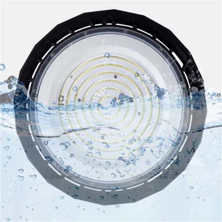
The fixture utilizes a massive Circular LED Chip Array. Instead of clustering dozens of chips in the center, the high-efficiency LED chips are arranged in multiple, concentric rings that span the entire surface of the light-emitting face.
The Optical Mathematics of Distributed Chips
The circular layout provides immense optical advantages. Because the chips are spread out, each individual chip requires less power and operates at a lower intensity. When the light from these distributed chips overlaps, they create a massive, continuous curtain of light.
This geometry drastically improves the Uniformity Ratio (U0)-the ratio of minimum illuminance to average illuminance across the working plane. A high U0 means there are no dark spots. The light effectively blankets the floor, penetrating deep into racking aisles and illuminating the vertical faces of machinery.
Thermal Synergy: Distributing the Heat Load
The large emitting area is not just an optical strategy; it is a thermal one. Concentrated chip clusters create extreme localized heat (hot spots). By distributing the chips across the circular array, the heat load is spread over a much larger surface area. Furthermore, because the chips extend outward toward the perimeter, the distance the heat must travel to reach the exterior heat sink is minimized. This lowers the peak LED junction temperature, ensuring the fixture maintains its brightness over its lifespan (minimizing lumen depreciation).
Optical Engineering: The PC Lens and Uniform Illumination
The Polycarbonate (PC) Lens: Optical Mixing and Diffusion
A circular array of discrete LED chips would still appear as hundreds of tiny, blinding dots if left unprotected. The secret to Uniform Illumination lies in the optical lens. This fixture utilizes a high-grade, UV-stabilized Polycarbonate (PC) Lens featuring a micro-structured surface.
The PC lens performs crucial optical functions:
Optical Mixing: The micro-structures blend the output of adjacent chips, transforming the discrete points of light into a single, seamless, and smooth beam.
Glare Reduction: The diffusion properties scatter the harsh light rays, reducing the Unified Glare Rating (UGR). This ensures that workers looking up at the fixture do not suffer from eye strain or momentary blindness.
Thermal Tolerance: PC is selected over PMMA or glass because it withstands continuous temperatures up to 120-130°C. In high-ceiling applications, fixtures are often run at high wattages, generating intense heat. PC will not warp, yellow, or crack under this thermal stress.
High CRI and Visual Comfort
Uniformity is not just about the spread of light; it is about the quality of that light. The circular array, combined with the PC lens, delivers a Color Rendering Index (CRI) of 80+. This high CRI ensures that colors appear natural, sharp, and vibrant. For quality control, color-coded wiring, or warning labels, this visual clarity is critical. The flicker-free operation (achieved via the Philips driver) eliminates stroboscopic effects, making high-speed machinery appear smooth and safe.
Vertical Illuminance: Illuminating the Racks
The broad beam angle produced by the large emitting area and the PC lens is specifically engineered to deliver high vertical illuminance. Instead of just illuminating the floor, the light wraps around the racking systems. This allows workers to read labels on the top shelves and allows automated systems (like AGVs and crane cameras) to function accurately.
The Supporting Architecture: Ensuring Brightness Never Fades
A large emitting area and a perfect lens are useless if the fixture overheat and degrades. The optical superiority of this UFO High Bay is supported by a hardcore engineering foundation.
The Philips Driver: The Electrical Heart
At the core of the fixture is a Genuine Philips Drive Power Supply. Industrial grids are plagued by voltage spikes and harmonic distortion. The Philips driver provides a fortress of electrical stability. It features a Power Factor (PF) of ≥0.95 and THD of <20%, ensuring that the power drawn from the grid is converted efficiently into usable light. More importantly, the driver is engineered with a >100,000-hour MTBF and built-in surge protection (4-6 kV), guaranteeing that the light will not suddenly fail due to a grid transient.
Integrated Die-Cast Aluminum and Air Convection Cooling
To dissipate the heat generated by the full-wattage operation of the circular array, the fixture relies on an Integrated Die-Cast Aluminum Shell. The monolithic casting (ADC12 alloy) features a thermal conductivity of 96-120 W/m·K, rapidly conducting heat away from the LED chips.
The exterior features a Hollow Radial Fin design that harnesses Air Convection Cooling. As the fixture heats up, hot air rises through the central chimney and escapes. This creates a negative pressure zone that forcefully draws cooler ambient air across the deep radial fins. This passive, self-sustaining cooling loop ensures the LED junction temperatures remain exceptionally low, preserving the brightness and preventing the lens from yellowing.
Procurement Framework: Evaluating High-Ceiling Lighting Solutions
The Flaw of Comparing Raw Lumens
When evaluating lighting for a high-ceiling facility, buyers must stop comparing "lumens" on the box. Lumens measure total light output, but they tell you nothing about how that light is distributed. A 30,000-lumen fixture with a clustered point source will produce terrible shadows.
Buyers must demand Illuminance (Lux) calculations for their specific facility layout. A lighting simulation (using DIALux or Relux) will show the Uniformity Ratio (U0). A premium fixture with a large emitting area will require fewer units to achieve the target lux levels, drastically reducing the total project cost.
Verifying the Optical Architecture
To ensure the fixture delivers true uniformity:
Check the LED layout. Is it a circular array spreading to the perimeter, or a tight central cluster?
Verify the lens material. A UV-stabilized PC lens with optical diffusion is required for glare control.
Look for the LM-79 and LM-80 reports to verify the actual light output and projected lifespan (L70/L80).
Calculating the Total Cost of Ownership (TCO)
The most critical factor for high-ceiling facilities is maintenance. Accessing a fixture mounted at 15 meters requires a scissor lift or a specialized high-reach lift, costing hundreds of dollars per use. A cheap fixture that fails in two years will destroy the project's ROI.
The combination of a Philips driver (>100,000 hours MTBF) and efficient thermal cooling means this UFO High Bay operates maintenance-free for a decade. The savings from avoided lift rentals, labor, and production downtime are immense, making the premium purchase price a highly profitable investment.
Conclusion: No Ceiling is Too High
The challenge of illuminating high-ceiling factories and warehouses is a test of optical physics. Traditional point-source fixtures fail because they concentrate too much light in one spot and cast deep shadows everywhere else.
This UFO High Bay Light represents the definitive engineering solution. By abandoning the clustered approach and adopting a massive Circular LED Chip Array, it transforms the fixture into a high-efficiency surface emitter. Combined with the optical diffusion of the PC Lens, it delivers flawlessly Uniform Illumination that reaches every corner, every rack, and every aisle. Supported by the electrical reliability of a Philips Driver and the thermal brilliance of Integrated Die-Cast Aluminum, this luminaire does not fear high ceilings. It conquers them, delivering safe, brilliant, and energy-efficient light for a decade of industrial operation.
How To Cooperate With Us?
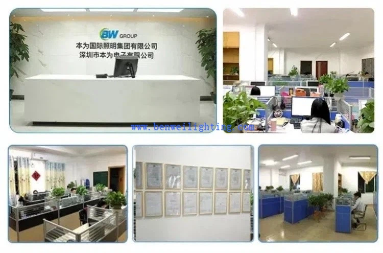
We are happy to have total control over the manufacturing process and the calibre of our products since we have our own facilities. Since we are producers rather than just brokers, we are dedicated to providing our customers with the best pricing. Since we are certain that the price and quality of our products are clear, we invite customers to see our samples first. Our commitment to quality and customer satisfaction drives us to continuously provide top-notch goods.
Our address
3rd Floor, 5th Building, Hebei Industrial Park, Hualian Community, Longhua District, Shenzhen, China