Introduction: Two Symptoms, One Underlying Question
The Field Reality Behind the "50,000-Hour" Label
A facility manager who replaces metal halide high bays with LED fixtures expects a decade of stable light. What frequently arrives instead is a more subtle degradation: the fixtures remain "on," but the space feels dimmer within three to five years, and a perceptible flicker may develop in the same population of luminaires. Neither symptom appears in the first month. Both emerge gradually, which is precisely why they are easy to underestimate until maintained illuminance falls below the threshold required for safe and productive work.
Industry reliability analysis identifies two dominant pathways behind this trajectory. Lumen depreciation is the slow decline of light output from the LED package and the phosphor system, accelerated dramatically by heat. Flicker originates not in the LED chip but in the driver's output current ripple, and it becomes visible when the ripple modulation depth exceeds what the human visual system can tolerate. The two pathways are distinct in mechanism, but they share a common determinant: the thermal and optical architecture of the luminaire governs how fast both failure modes advance.
Why the Chip-Lens Pairing Is the Relevant Unit of Analysis
Specification sheets treat the LED chip and the lens as separate line items. In the physics of the assembled fixture, they are not separable. The chip layout determines the spatial distribution of heat and light; the lens determines how that light is shaped, mixed, and delivered to the task plane. A thermally aggressive chip layout degrades faster regardless of lens quality. A poorly designed lens can waste the output of a well-made chip through absorption, glare, or non-uniformity.
The circular LED array paired with a PC lens is not an aesthetic choice. It is an architecture in which circular symmetry serves both thermal spreading and optical uniformity simultaneously, and the lens material is selected for the thermal environment the chip array creates. This article examines each component's contribution and then the system-level interaction that neither component delivers in isolation.
The Circular LED Chip Array: Thermal Spreading and Optical Symmetry
Junction Temperature as the Master Variable in Lumen Depreciation
The useful life of an LED is conventionally defined by the L70 metric: the point at which light output has declined to 70% of its initial value. For a population of luminaires, L70 is expressed as the time at which half the population has crossed that threshold. The laboratory basis for this metric is LM-80 testing of the LED package at controlled case temperatures, extrapolated through the TM-21 projection method.
The critical fact obscured by a single "50,000 hours" number is that L70 is not an intrinsic property of the chip. It is a function of junction temperature. The same LED package operated at a lower junction temperature will exhibit a dramatically longer projected lifetime; the same package at a higher junction temperature will reach L70 years earlier. In the field, the junction temperature is set not by the chip datasheet but by the luminaire's ability to conduct heat away from the LED board and reject it to the ambient air.
Why Circular Layout Changes the Heat Flow Path
A concentrated chip cluster - common in low-cost designs that place a dense array in the center of the fixture - creates a thermal hot spot at the center of the board. Heat must travel radially outward through the board material and the thermal interface before reaching the housing fins. The longer the conduction path, the higher the thermal resistance, and the higher the steady-state junction temperature for the same electrical input.
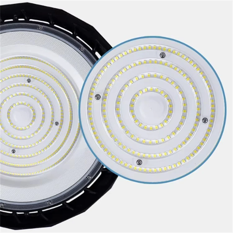
A circular array distributes the LED packages across multiple concentric rings extending toward the perimeter of the light-emitting surface. This layout produces two thermal benefits. First, heat generation is spread over a larger area, reducing the peak heat flux at the center. Second, the distance from any individual chip to the nearest heat-sink material is shortened, because the perimeter of the board is itself closer to the housing fins. The result is a lower peak junction temperature and a narrower temperature distribution across the array, which translates directly into slower lumen depreciation and more uniform color stability over time.
The Optical Consequence of Circular Symmetry
The circular layout is not only a thermal strategy. A UFO-form high bay with properly spaced chips arranged in concentric rings behaves as a surface emission device rather than a point source. This distinction matters for illumination quality. A concentrated source produces a bright core and a rapid falloff toward the edges of the illuminated area, forcing higher fixture density to compensate. A distributed circular source produces a more uniform illuminance distribution on the floor, reduces harsh shadows beneath machinery, and allows wider fixture spacing without dark zones.
In warehouses and production halls, this optical symmetry has a practical maintenance implication: fewer fixtures are needed to achieve the target maintained illuminance, and each fixture operates at a lower drive current for the same delivered light - which further reduces junction temperature and slows depreciation. The circular layout therefore participates in a positive feedback loop: better uniformity enables lower drive levels, and lower drive levels extend lumen maintenance.
The PC Lens: Optical Control, Structural Protection, and Thermal Compatibility
Why Polycarbonate, Not PMMA
The dominant optical materials for LED lenses are PMMA (acrylic) and polycarbonate. PMMA offers higher light transmittance, typically 92–93%, compared with PC's 88–90% . On transmittance alone, PMMA appears superior. The decisive difference for a high bay application is thermal tolerance. PMMA's practical operating ceiling is approximately 80–90°C, while polycarbonate withstands continuous exposure to 120–130°C .
An industrial high bay operating at 150–200 W in an unconditioned warehouse places the lens in close proximity to an LED board and a heat sink that routinely reach surface temperatures beyond PMMA's safe range. A lens that softens, warps, or yellows under thermal load no longer performs its optical function; it becomes a source of non-uniformity and color shift. Polycarbonate's higher glass-transition temperature preserves optical geometry and dimensional stability over the service life of the fixture. For a luminaire intended to operate for a decade in a demanding thermal environment, the marginal transmittance deficit of PC relative to PMMA is a controlled trade-off, not a compromise.
Optical Function: Diffusing the Source Without Sacrificing Output
The PC lens in this architecture is not a simple transparent cover. It is a micro-structured optical element whose surface geometry redistributes the output of the discrete chip array into a smooth, uniform beam. Without such a lens, each individual chip would be visible as a point of brightness, producing glare and a "dotted" illuminance pattern on the floor below. The lens performs two functions simultaneously: it mixes the output of adjacent chips so that the array behaves as a single extended source, and it shapes the angular distribution so that light is directed toward the task plane rather than scattered into the upper hemisphere or directly into the eyes of workers.
Polycarbonate is capable of being moulded with high-precision micro-optics, and optical-grade PC lenses are specified in industrial high bay fixtures to achieve glare ratings consistent with EN 12464-1 requirements, with uniformity ratios that meet or exceed the standards for industrial task areas. The lens material's optical clarity must be maintained over time; UV-stabilized PC grades preserve light transmission and resist yellowing under prolonged exposure to the blue-rich output of the LED source.
Structural and Environmental Co-Function
The PC lens also serves as the primary environmental barrier for the optical cavity. In a dusty foundry or a washdown food-processing facility, particulate ingress onto the LED board would rapidly degrade output and accelerate thermal failure. The lens is sealed to the housing, and polycarbonate's impact resistance - approximately 30 times that of PMMA and 250 times that of glass - prevents cracking or fracture from accidental contact, vibration, or thermal cycling. A cracked lens is not merely a cosmetic defect; it is a breach in the thermal and optical system that exposes the chips and the driver cavity to the environment.
The Lens as a Flicker Mitigator
Flicker originates in the driver's current ripple, not in the lens. The LED's light output modulates in near-linear proportion to the driving current, so a ripple of a given percentage produces a comparable modulation in luminous flux. IEEE 1789-2015 recommends a maximum flicker modulation of 10% at 120 Hz to avoid health risks to viewers, and well-designed drivers achieve modulation levels of 2% or less.
The lens does not eliminate ripple. What the lens architecture does is spatially integrate the output of many chips distributed across the circular array. When the individual sources are numerous, spatially separated, and optically mixed by a diffusing lens, the residual temporal modulation perceived by an observer is attenuated relative to the modulation of any single chip. The circular array and the PC lens therefore provide a second line of defense against the perception of flicker, even as the driver remains the primary determinant of ripple magnitude. The practical result is that a fixture with a well-regulated driver and a properly diffused circular optical system is less likely to produce visible flicker at end of life, when driver capacitors have aged and ripple has increased.
System-Level Synergy: Why the Combination Outperforms the Sum of Its Parts
Thermal Feedback: The Lens Protects the Thermal Path
The PC lens's thermal stability is not only a property of the lens itself. By maintaining its geometry at elevated temperatures, the lens preserves the seal and the optical alignment of the LED cavity. A deformed lens can create localized hot spots by altering the convective environment around the board, or by allowing dust to accumulate unevenly on the inner surface. Polycarbonate's dimensional stability under thermal load protects the thermal spreading benefit of the circular chip layout over the full service life of the fixture.
Optical Feedback: Uniformity Reduces Thermal Stress
The uniform illuminance distribution produced by the circular array and the diffusing PC lens allows the lighting designer to specify fewer fixtures or lower drive currents for the same maintained illuminance target. Every reduction in required drive current lowers the junction temperature of the chip array. A lower junction temperature slows lumen depreciation, and it also reduces the thermal stress on the driver's electrolytic capacitors, which are the components most sensitive to ambient temperature. The optical design therefore feeds back into the electrical and thermal reliability of the entire system: better uniformity reduces the electrical burden, and a lower electrical burden extends the life of both the LEDs and the driver.
The Economic Translation: Maintained Output, Not Sticker Price
The commercial argument follows directly from the physics. A commodity high bay that reaches L70 within 15,000–25,000 hours - a realistic outcome for budget fixtures in hot, dusty industrial environments - imposes a replacement cycle that erases its initial price advantage. A fixture whose circular thermal architecture and stable PC optics keep junction temperatures within the design window can maintain useful output well beyond 50,000 hours, with a slower rate of depreciation and a lower probability of visible flicker before end of life.
The relevant cost metric is not dollars per initial lumen. It is total cost of ownership per maintained lumen, where the denominator accounts for the light actually delivered in year five, year seven, and year ten, and the numerator accounts for the fixture price plus the labor, access equipment, and production disruption of each replacement event. In high-ceiling installations, the labor and lift cost of a single replacement frequently exceeds the original fixture price. A chip-lens architecture that delays that event by five years is a maintenance budget instrument, not merely a lighting component.
Verification Framework: How to Confirm the Combination Is Real
Three Questions the Spec Sheet Should Answer
First, what is the LED chip layout, and is it circular and distributed? A product that claims "uniform light" but places a dense cluster of chips in the center of the board is relying on the lens to compensate for a thermally and optically inferior source geometry. The layout should extend the chip array toward the perimeter of the light-emitting surface.
Second, what is the lens material and its rated continuous operating temperature? "PC lens" is a starting point, not a complete specification. UV-stabilized optical-grade PC with a continuous temperature rating above the fixture's maximum measured lens-surface temperature is the relevant criterion. A lens rated at 80–90°C in a 150 W high bay is a thermal mismatch.
Third, what is the flicker performance at end of life, not just at zero hours? The driver's ripple cancellation design determines flicker, and capacitor aging increases ripple over time. A specification that reports modulation depth below 5% at beginning of life, combined with a driver topology designed for low output ripple, provides a meaningful reliability signal.
The Procurement Conclusion
The circular LED array and the PC lens are not decorative features or cost-reduction substitutions. They are failure-mode–specific engineering choices: the circular layout attacks lumen depreciation at its thermal root by spreading heat and lowering peak junction temperature while simultaneously improving illuminance uniformity; the PC lens sustains optical performance in the thermal environment that the chip array creates, and its diffusing structure softens the perception of residual driver ripple.
A fixture built around this combination is more likely to remain bright, uniform, and stable across the decade in which its cost is amortized. The purchasing question is therefore not whether the fixture is "cheaper per watt" on the invoice. It is whether the luminaire will still be delivering its rated function when the maintenance budget is least able to absorb a replacement cycle.
How To Cooperate With Us?
We are happy to have total control over the manufacturing process and the calibre of our products since we have our own facilities. Since we are producers rather than just brokers, we are dedicated to providing our customers with the best pricing. Since we are certain that the price and quality of our products are clear, we invite customers to see our samples first. Our commitment to quality and customer satisfaction drives us to continuously provide top-notch goods.
Our address
3rd Floor, 5th Building, Hebei Industrial Park, Hualian Community, Longhua District, Shenzhen, China